
Cyclone refrigerant branching device

A branching and refrigerant technology, applied in the direction of fluid circulation arrangements, refrigerators, refrigeration components, etc., can solve the problems of high pressure and difficulty in securing air-conditioned space, and achieve the effects of flexible installation, simple structure, and reduced processing difficulty

Inactive Publication Date: 2012-07-25
HUNAN UNIV OF SCI & TECH
View PDF5 Cites 2 Cited by
  • Summary
  • Abstract
  • Description
  • Claims
  • Application Information

AI Technical Summary

Problems solved by technology

This kind of shunt body generates turbulence by throttling the refrigerant, so that the two-phase refrigerant is fully mixed, and there is a large pressure drop. At the same time, when the refrigerant flow rate changes greatly, the throttling aperture needs to be adjusted accordingly. raises a series of questions
In addition, when installing the pressure drop type branch body, attention must also be paid to the arrangement of the outlet in the direction of gravity as much as possible to reduce the uneven liquid separation caused by the difference in gas-liquid density, but it is often difficult to obtain in a small air-conditioned space. ensure

Method used


Image

  • Cyclone refrigerant branching device
  • Cyclone refrigerant branching device
  • Cyclone refrigerant branching device

Examples


Embodiment Construction

[0015] The present invention will be further described in detail below in conjunction with the accompanying drawings and embodiments.

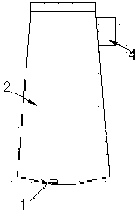
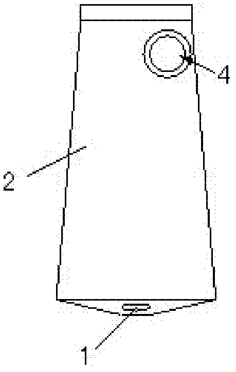
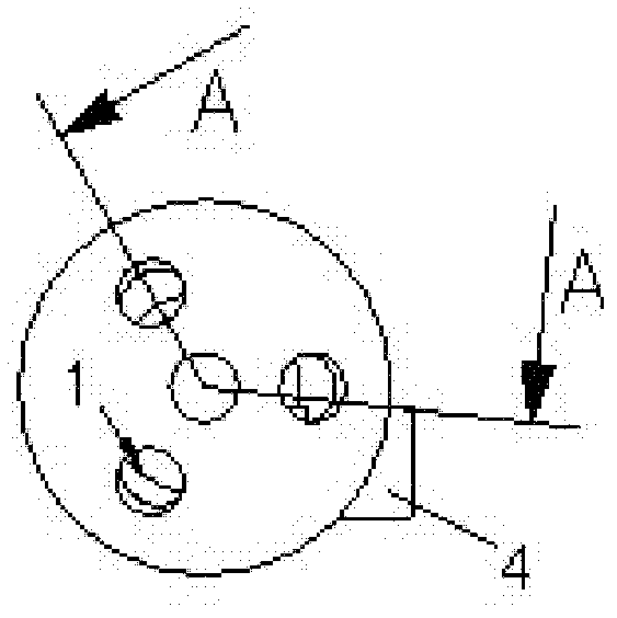
[0016] see figure 1 , figure 2 , image 3 , Figure 4 and Figure 5 , this embodiment includes a cylindrical body 2 . From Figure 4 and Figure 5 It can be seen from the figure that the right end surface of the main body 2 is closed, and there are three branch outlet holes 1 on the left end surface of the main body 2; it can also be seen from the figure that the left end surface of the main body 2 is a slope protruding toward the center of the main body, and the three branch outlet holes 1 are evenly distributed around the circumference of the left end face, and the center line of the branch outlet hole 1 is inclined outward relative to the center line of the main body 2, which facilitates the installation of each branch pipe on each branch outlet hole 1. The inner cavity of the main body 2 is a shunt inner cavity 3 , and the shun...


PUM


Abstract

The invention belongs to the technical field of air-conditioners, and particularly relates to a cyclone refrigerant branching device for a heat exchanger of an air-conditioner, which comprises a cylindrical body with one end face closed and the other end face provided with a plurality of branch outlet holes. An inner cavity of the body is an inner branching cavity and communicated with the branch outlet holes. The body side wall at the closed end of the body is provided with a tangential refrigerant inlet hole, and the center line of the tangential refrigerant inlet hole is perpendicular to the center line of the body but not intersected with the same, and close and parallel to the tangent line of the inner wall of the branching cavity to enable refrigerant in a liquid supply pipe inserted into the refrigerant inlet hole to tangentially flow in the branching cavity. The cyclone refrigerant branching device is effective in branching, less susceptible to gravity, flexible in mounting, simple in structure and economically and technically advantageous as processing difficulty is lowered.

Description

technical field [0001] The invention belongs to the technical field of air conditioners, and in particular relates to a swirl refrigerant branch body for an air conditioner heat exchanger. Background technique [0002] In the refrigeration system, in order to ensure the best heat exchange effect and refrigerant flow rate in the refrigerant pipeline, the compact air cooler with direct evaporative liquid supply must adopt the form of parallel connection of multi-channel coils, so that the best exchange rate can be achieved on the one hand. The thermal effect, on the other hand, can maintain the optimum refrigerant flow rate and limit the pressure drop within a certain range. The refrigerant coming out of the expansion valve or capillary tube is usually a mixture of gas-liquid two-phase bubble flow or soft plug flow type. The purpose of the branch body is to fully mix the two-phase refrigerant and distribute it to each coil in equal amounts. to go. [0003] At present, air co...

Claims


Application Information

Patent Timeline
Patent Type & Authority Applications(China)
IPC IPC(8): F25B41/00
Inventor 李孔清邹声华
Owner HUNAN UNIV OF SCI & TECH
Learn More