
System-level error parameter field calibration method of strapdown inertial navigation optical fibre gyro

A fiber optic gyroscope and strapdown inertial navigation technology, applied in the field of navigation, can solve the problems of long calibration time, large amount of data processing, large amount of matrix calculation, etc., and achieve the effect of strong real-time performance, strong flexibility, and reduced dimension.

Inactive Publication Date: 2012-07-25
HARBIN ENG UNIV
View PDF0 Cites 15 Cited by
  • Summary
  • Abstract
  • Description
  • Claims
  • Application Information

AI Technical Summary

Problems solved by technology

The discrete calibration method has the disadvantages of long calibration time, calibration accuracy is too dependent on the accuracy of the turntable, and a large amount of data processing.
However, the system-level calibration method with speed as the observation quantity has more state quantities of the filter state equation, a large amount of matrix calculation, takes up a lot of navigation computing resources, and has higher performance requirements for the navigation computer.
However, the use of navigation computers with high performance and high computing frequency will increase the cost of the entire strapdown inertial navigation system, which will bring problems to the widespread use in engineering

Method used


Image

  • System-level error parameter field calibration method of strapdown inertial navigation optical fibre gyro
  • System-level error parameter field calibration method of strapdown inertial navigation optical fibre gyro
  • System-level error parameter field calibration method of strapdown inertial navigation optical fibre gyro

Examples


Embodiment Construction

[0038] The present invention is described in more detail below in conjunction with accompanying drawing example:

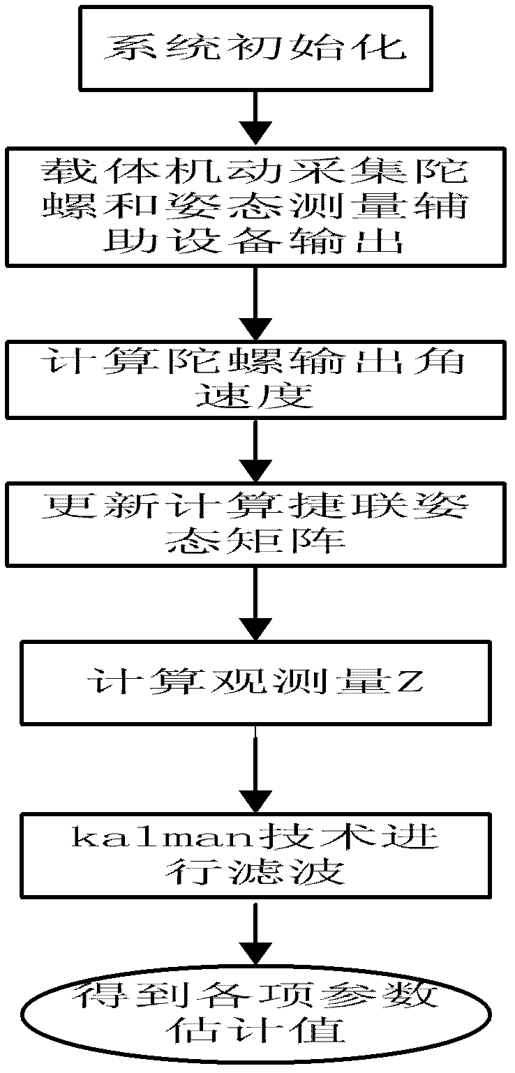
[0039] combine figure 1 ~2, the strapdown inertial navigation fiber optic gyro system-level error parameter field calibration method of the present invention comprises the following steps:

[0040] Step 1. Connect the fiber optic gyro strapdown inertial navigation system to be calibrated with the attitude measurement auxiliary device provided on site through a data transmission cable to ensure smooth data transmission between the two devices. Make sure that the angular velocity measurement value output by the fiber optic gyroscope is consistent with the attitude angle of the carrier output by the attitude measurement auxiliary device, and can be saved by the computer.

[0041] Step 2. The FOG strapdown inertial navigation system performs initial alignment, determines the initial attitude of the coordinate system where the gyroscope is located, and obtains the ini...


PUM


Abstract

The invention aims to provide a system-level error parameter field calibration method of a strapdown inertial navigation optical fibre gyro. The system-level error parameter field calibration method comprises the following steps: an optical fibre gyro strapdown inertial navigation system is communicated with auxiliary attitude measuring equipment, and the optical fibre gyro strapdown inertial navigation system can carry out initial alignment; the output values of the optical fibre gyro and the auxiliary attitude measure equipment are collected, the output value of the optical fibre gyro is converted into the angular speed of a coordinate system of the gyro relative to an inertial system and the angular speed is substituted into a strapdown inertial navigation equation to obtain a transition matrix of the optical fibre gyro relative to the local geographic coordinate system; according to a real-time attitude angle provided by the auxiliary attitude measuring equipment, a true attitude transition matrix T is obtained and an attitude error matrix and a system real-time attitude error angle are obtained further; and the attitude error matrix and the system real-time attitude error angle are substituted into a system level filtering state calibration equation of the optical fibre gyro to estimate each error parameter so as to finish identification. The system-level error parameter field calibration method provided by the invention has strong flexibility in the selection of a calibration path, and greatly reduces the dimension of a filter state equation.

Description

technical field [0001] The invention relates to a calibration method in the field of navigation. Background technique [0002] The inertial navigation system is a navigation device that uses gyroscopes and accelerometers to measure the angular motion and linear motion of the carrier, and obtains the instantaneous attitude, velocity and position of the carrier through integral calculations. It completely relies on its own sensitive devices to complete navigation tasks without relying on any external Information does not radiate any energy outside, it is a completely autonomous navigation system, so it has the advantages of good concealment, anti-interference, and not limited by any weather conditions. Due to the above advantages, it has been widely used in aviation, aerospace, navigation and many other fields. [0003] The fiber optic gyroscope has the advantages of high precision, fast start-up, large dynamic range, anti-vibration shock and low cost, and is the development ...

Claims


Application Information

Patent Timeline
IPC IPC(8): G01C25/00
Inventor 高伟盛宏媛周广涛宋明哲奔粤阳徐博王秋莹吴晓张义娄少锋
Owner HARBIN ENG UNIV
Learn More