
Air pressure loading valve positioner test bed

A technology of valve positioner and test bench, which is applied in the testing of machines/structural components, instruments, mechanical components, etc. It can solve the problems of bulky, uneven wear of loading devices, high price, etc., and achieve simple loading methods and eliminate The effect of backlash and quick connection

Inactive Publication Date: 2012-07-25
SHENZHEN MAXONIC AUTOMATION CONTROL CO LTD
View PDF6 Cites 18 Cited by
  • Summary
  • Abstract
  • Description
  • Claims
  • Application Information

AI Technical Summary

Problems solved by technology

[0005] For motion tests within 90° at low motion speeds, the electromagnetic controllability for low-speed loads is poor, the hydraulic load table is large in size, and additional liquid pressurization equipment is required
[0006] And no matter electromagnetic or hydraulic load is usually suitable for multi-turn rotary motion test, for this kind of load friction only in the range of 1 / 4 turn, it will cause unilateral force, uneven wear of the load device, and accelerated damage
[0007] Regardless of whether the test benches on the market use hydraulic loading or electromagnetic / magnetic powder loading, the loading device needs to be purchased separately, equipped with energy, bulky, and expensive, and is suitable for multi-rotation equipment testing

Method used


Image

  • Air pressure loading valve positioner test bed
  • Air pressure loading valve positioner test bed
  • Air pressure loading valve positioner test bed

Examples


Embodiment Construction

[0036] Embodiments of the present invention will be described in detail below in conjunction with the accompanying drawings.

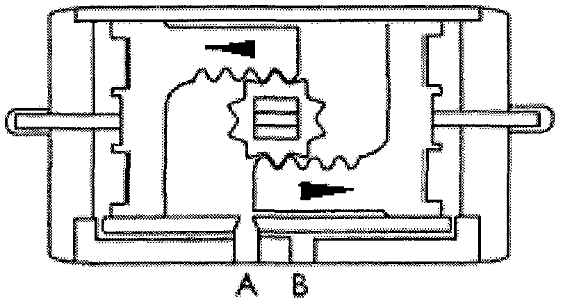
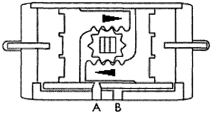
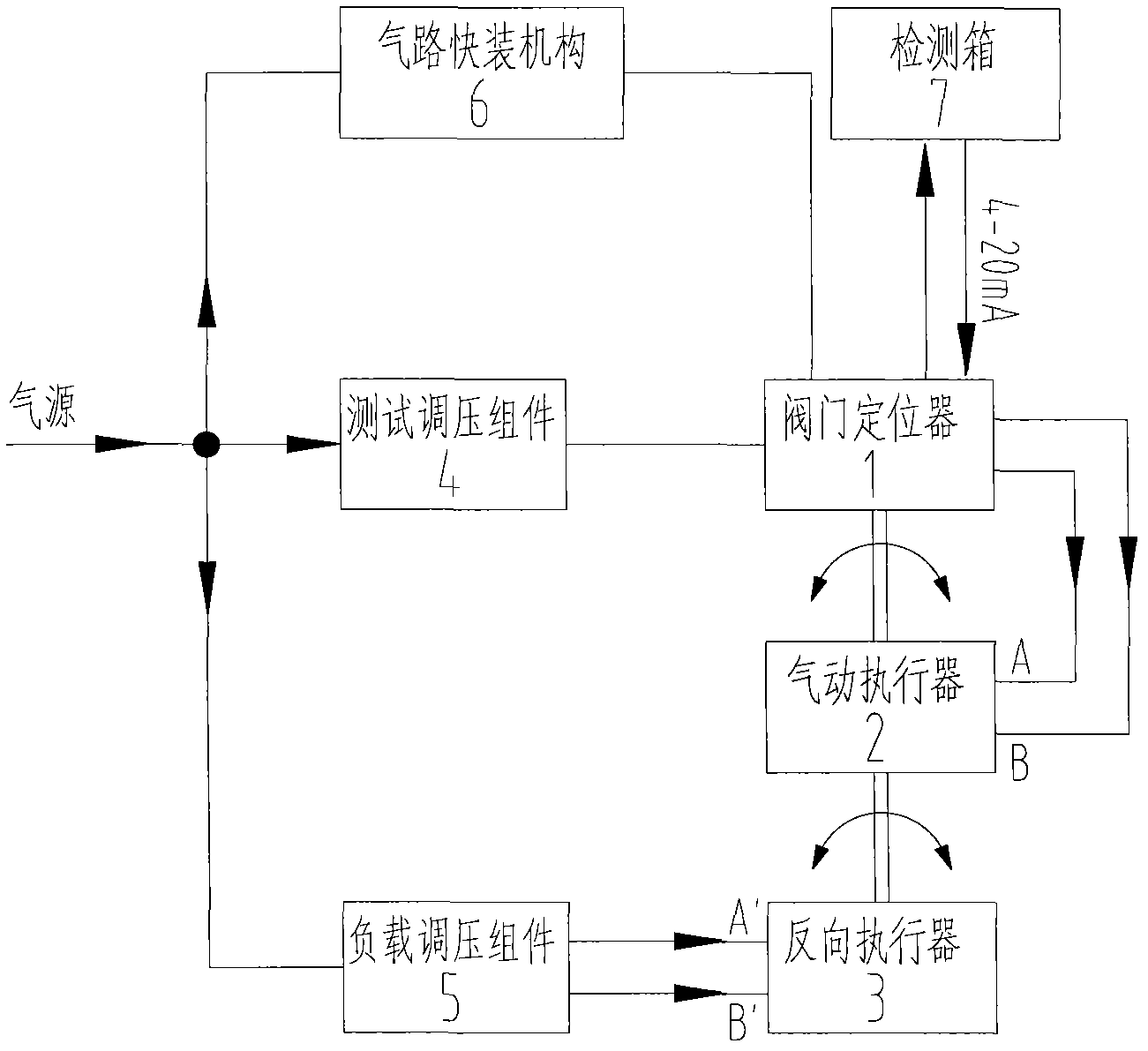
[0037] The present invention utilizes two rotary quarter-stroke double-acting pneumatic actuators as a double-acting intelligent valve positioner 1 testing load for an air pressure-loaded valve positioner test bench.

[0038] This test bench includes a control mechanism pneumatic actuator 2 that is matched with the intelligent valve positioner 1 under test, a pneumatic loading system composed of a small actuator used in reverse to simulate the load of the controlled valve, and a quick connection An air circuit quick installation mechanism for the air cavity of the pneumatic actuator 2 and the air circuit interface of the tested valve positioner 1, and a hysteresis elimination mechanism for eliminating the rotary clearance between the tested valve positioner and the pneumatic actuator.

[0039] The structure of the rotary quarter-turn double-acting pneu...


PUM


Abstract

The invention discloses an air pressure loading valve positioner test bed which comprises a vacuum control mechanism pneumatic executer, an air pressure loading system, a test pressure regulation component and a detection box, wherein the vacuum control mechanism pneumatic executer is matched with a tested valve positioner; the air pressure loading system is connected with an output end of the pneumatic executer and used for stimulating the working conditions of the controlled valve; the test pressure regulation component provides the test air pressure to the tested valve positioner; and the detection box is connected with the valve positioner. The air pressure loading system comprises a reverse executer and a load pressure regulation component, wherein the reverse executer is rotatably connected with the output end of the pneumatic executer; and the load pressure regulation component provides the loaded air pressure to the reverse executer. By adjusting the output pressure of the load pressure regulation component, the reverse torque of the reverse executer can be changed, and the change of the load acting on the output end of the pneumatic executer is realized. The air pressure loading valve positioner test bed disclosed by the invention has the advantages that: the air pressure loading system composed of reversely-used small executers is used for stimulating the working conditions of the load of the valve controlled on the site, so that the test conditions of the valve positioner are more close to the really-used actual environment.

Description

technical field [0001] The invention relates to the technical field of testing equipment, in particular to a pneumatic loading test bench for testing a valve positioner. [0002] It is suitable for valve positioner manufacturers as test equipment for simulating the scene, especially suitable for testing rotary rotary positioners. Applicable for actuator load testing up to 90° rotation. Background technique [0003] Existing load test benches generally use friction as the load, whether it is electromagnetic / magnetic powder loading or hydraulic disc friction loading, friction is used as the test load. [0004] The overall purchase price of the existing load test bench is relatively high, and the loads are all professional braking equipment, which generally requires an additional power source, such as electromagnetic and hydraulic pressure. [0005] For motion tests within 90° at low motion speeds, the electromagnetic controllability for low-speed loads is poor, the hydraulic...

Claims


Application Information

Patent Timeline
Patent Type & Authority Applications(China)
IPC IPC(8): G01M13/00
Inventor 傅宇晨袁敏勋袁菲冯光瑜
Owner SHENZHEN MAXONIC AUTOMATION CONTROL CO LTD
Learn More