Phase compensation controller

A phase compensation and controller technology, applied in the electronic field, can solve the problems of large chip area, etc., and achieve the effects of reducing area, saving cost, and reducing the size of resistance

Active Publication Date: 2012-07-25
ZHEJIANG UNIV
View PDF6 Cites 5 Cited by
  • Summary
  • Abstract
  • Description
  • Claims
  • Application Information

AI Technical Summary

Problems solved by technology

[0014] The invention provides a phase compensation controller, which solves the problem that the chip occupies too much area in the process of integrating the chip of the controller in the prior art

Method used


Image

  • Phase compensation controller
  • Phase compensation controller
  • Phase compensation controller

Examples


Embodiment Construction

[0048] Due to the amplification effect of the amplifier, the distributed capacitance or parasitic capacitance between the input and output of the inverting amplifier circuit will expand the capacitance value equivalent to the input terminal of the amplifier by 1+K times. This is the Miller effect in the general sense. ). In addition, the impedance between any input and other highly amplified sections can also change the input impedance of the amplifier through the Miller effect.

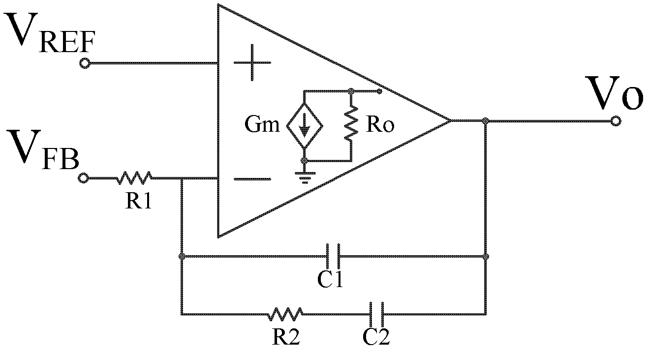
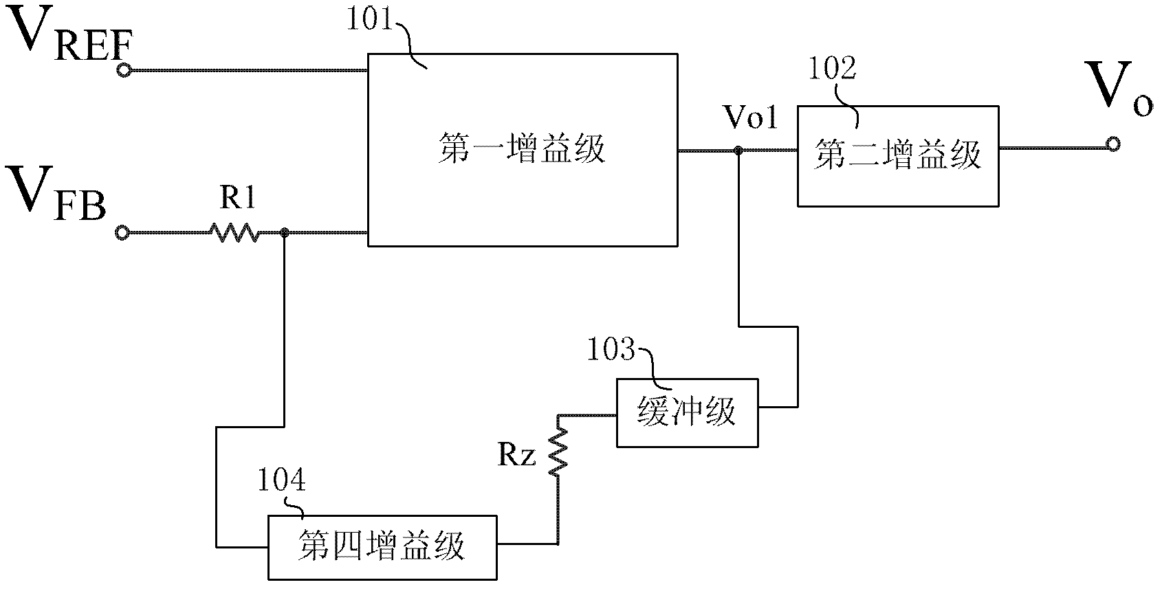
[0049] The present invention is based on the above principles, and in combination with the conventional phase compensation controller of the prior art, provides a phase compensation controller whose transfer function is as follows:

[0050] Gvc = v o v FB = - A ( 1 + ...


PUM


Abstract

The invention discloses a phase compensation controller, which comprises a first gain stage, a second gain stage, a second capacitor coupled between the second gain stage output end and the ground, a buffer stage, a resistor Rz, a fourth gain stage and a resistor R1 at the normal phase input end of one gain stage, wherein the first gain stage and the second gain stage are connected in series, and the buffer stage, the resistor Rz and the fourth gain stage form a feedback loop together with the first gain stage. The fourth gain stage further comprises a first capacitor, a first current amplifier and a second current amplifier which are in couple connection with the input end, and the first current amplifier is used for amplifying current Ic passing through the first capacitor by K times to obtain current Ic'. The second current amplifier is used for amplifying the current Ic passing through the first capacitor by K times to obtain current Ic''. The phase compensation controller greatly decreases the achieving area and saves the cost of integrated chips.

Description

technical field [0001] The invention relates to the field of electronic technology, in particular to a phase compensation controller. Background technique [0002] The switching power supply system is a closed-loop voltage regulation system, such as figure 1 As shown, it consists of two parts, the power conversion circuit and the control loop. The control loop includes the phase compensation controller. After the parameters of the power conversion circuit and the structure of the phase compensation controller are selected, the phase compensation controller can be determined by parameters to ensure the dynamic performance indicators of the system, such as the relative stability of the system, the rapidity of dynamic response, and the ability to suppress the sinusoidal disturbance of the power supply voltage and load small signal, that is, the phase compensation network of the switching power supply system is realized. [0003] The voltage stability of the switching power sup...

Claims


Application Information

Patent Timeline
Patent Type & Authority Applications(China)
IPC IPC(8): G05F1/56
Inventor 赵梦恋孙鹏吴晓波杨瑾邓琳
Owner ZHEJIANG UNIV
Why Eureka
Try Eureka