Efficient composite energy storage system for vehicles

A composite energy storage and energy storage system technology, which is applied in the field of new energy vehicle energy storage systems, can solve the problems of inability to charge and discharge, the advantages and limitations of super capacitors, and the inability to make full use of super capacitors, so as to reduce the burden and improve economic performance and power. Performance, the effect of reducing the difficulty of control

Active Publication Date: 2014-03-05
TSINGHUA UNIV
View PDF3 Cites 2 Cited by
  • Summary
  • Abstract
  • Description
  • Claims
  • Application Information

AI Technical Summary

Problems solved by technology

This structure avoids the loss caused by the energy entering and exiting the bidirectional DC / DC converter, but its disadvantage is that the capacity of the supercapacitor cannot be fully utilized: because the change of the terminal voltage of the power battery with the SOC is a hard characteristic (that is, the SOC varies greatly, However, the terminal voltage does not change much), and the change of the terminal voltage of the supercapacitor with the SOC is a soft characteristic (that is, when the SOC changes, the terminal voltage also has a large change), so when the system is working, the voltage of the DC bus The power battery is always maintained within a very narrow range of change, resulting in the terminal voltage of the super capacitor and the corresponding SOC also changing within a very narrow range, which cannot be fully charged and discharged, which greatly limits the advantages of the super capacitor

Method used


Image

  • Efficient composite energy storage system for vehicles
  • Efficient composite energy storage system for vehicles
  • Efficient composite energy storage system for vehicles

Examples


Embodiment Construction

[0025] The present invention will be described in detail below in conjunction with the accompanying drawings and embodiments.

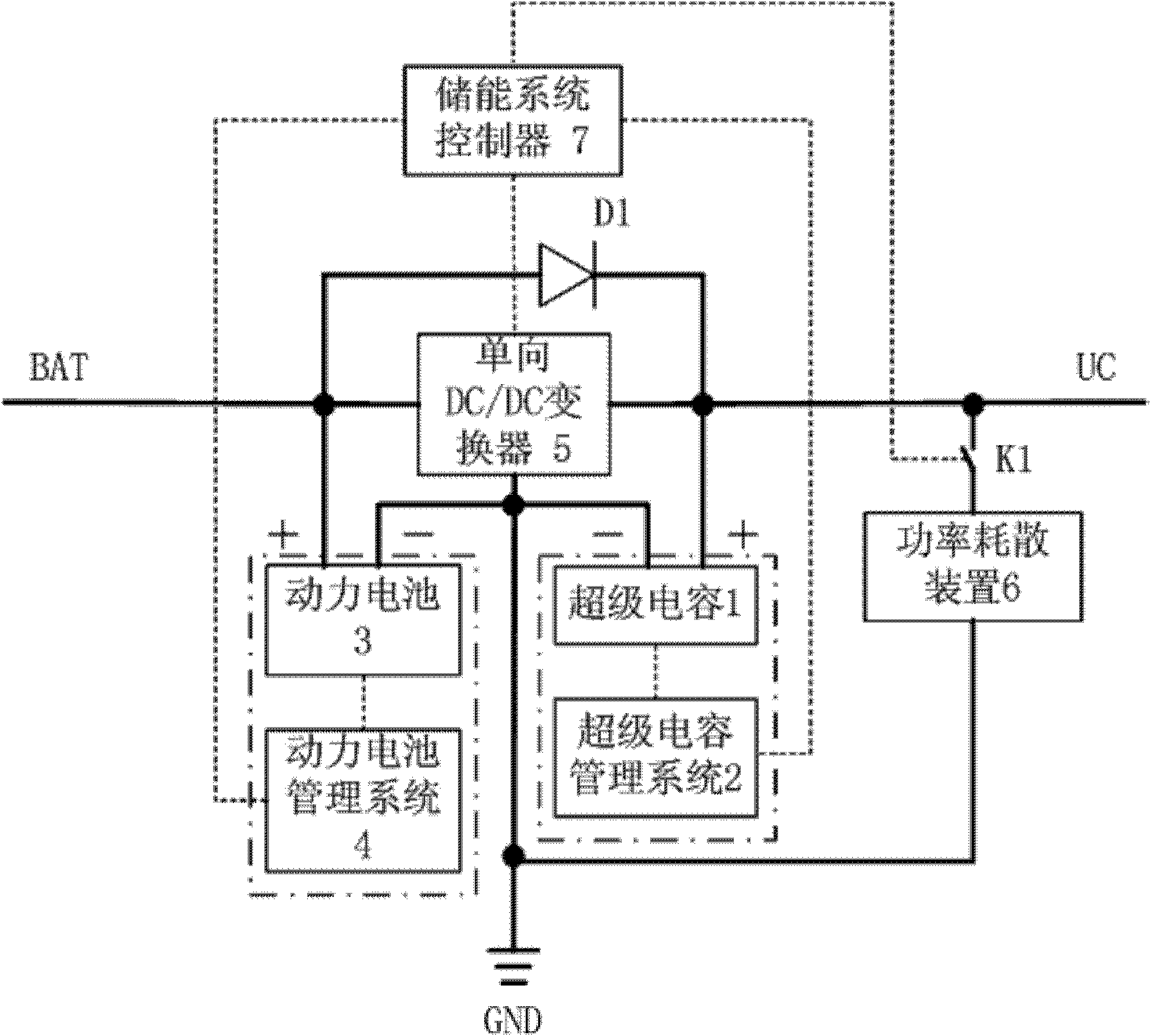
[0026] Such as image 3 As shown, the present invention provides a high-efficiency composite battery for vehicles that utilizes the supercapacitor 1 in the prior art and the supercapacitor management system 2 for controlling its work, the power battery 3 and the power battery management system 4 for controlling its work. The energy storage system includes a unidirectional DC / DC converter 5 , a power diode D1 , a function dissipation device 6 , a power switch K1 and an energy storage system controller 7 .

[0027] The unidirectional DC / DC converter 5 is connected in parallel with the power diode D1, the anode of the power diode D1 is connected to the output end of the unidirectional DC / DC converter, and the cathode of the power diode D1 is connected to the input end of the unidirectional DC / DC converter; the power diode D1 The anode of the power diode D...


PUM


Abstract

The invention relates to an efficient composite energy storage system for vehicles, which comprises a super capacitor, a super capacitor management system, a power battery, a power battery management system, a one-way DC / DC converter, a power diode, a power dissipation device, a power switch and an energy storage system controller, wherein the super capacitor management system is used for controlling operation of the super capacitor, and the power battery management system is used for controlling operation of the power battery. The one-way DC / DC converter is in parallel connection with the power diode, an anode of the power diode is connected with an output end of the one-way DC / DC converter, a cathode of the power diode is connected with an input end of the one-way DC / DC converter, the anode of the power diode is further connected with an anode of the power battery, and the cathode of the power diode is further connected with an anode of the super capacitor. A cathode of the power battery, a cathode of the super capacitor and the one-way DC / DC converter are in common ground, and the power switch and the power dissipation device which are in serial connection are further connected between the anode and the cathode of the super capacitor. The power battery management system, the super capacitor management system, the power switch and the one-way DC / DC converter are coordinately controlled by the energy storage system controller. The efficient composite energy storage system is widely applicable to energy storage systems of new energy vehicles.

Description

technical field [0001] The invention relates to a new energy vehicle energy storage system, in particular to a high-efficiency composite energy storage system for vehicles based on supercapacitors and power batteries. Background technique [0002] With the increasingly severe energy crisis and global warming, energy conservation and emission reduction has become an urgent task for the global automotive industry, and new energy vehicles have therefore developed rapidly. Hybrid vehicles and pure electric vehicles are the most promising new energy vehicles. Two categories of development prospects. The power system of a hybrid vehicle is mainly composed of a power unit and an energy storage system. The function of the power unit is to convert the chemical energy of the vehicle fuel into mechanical energy and finally into electrical energy (diesel engine or gasoline engine), or directly into electrical energy (fuel cell engine); the role of the energy storage system is to provid...

Claims


Application Information

Patent Timeline
Patent Type & Authority Patents(China)
IPC IPC(8): H02J15/00H02J7/00
Inventor 李建秋徐梁飞帅志斌欧阳明高卢兰光杨福源
Owner TSINGHUA UNIV
Why Eureka
Try Eureka