Mixed type excitation permanent magnet, rotor for rotating electric machine using same and generator

A technology for permanent magnets and rotating motors, applied to permanent magnets, magnetic circuit rotating parts, magnetic circuits, etc., to achieve the effects of reducing magnet input, miniaturization, and reducing eddy current loss

Inactive Publication Date: 2012-07-25
YASKAWA DENKI KK +1
View PDF6 Cites 7 Cited by
  • Summary
  • Abstract
  • Description
  • Claims
  • Application Information

AI Technical Summary

Problems solved by technology

[0006] However, since the permanent magnet described in Patent Document 1 is composed of only one kind of high Hcj ma

Method used


Image

  • Mixed type excitation permanent magnet, rotor for rotating electric machine using same and generator
  • Mixed type excitation permanent magnet, rotor for rotating electric machine using same and generator
  • Mixed type excitation permanent magnet, rotor for rotating electric machine using same and generator

Examples


no. 1 Embodiment approach

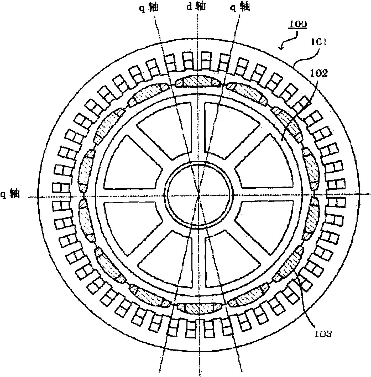
[0032] First, refer to figure 1 The configuration of the permanent magnet generator according to the first embodiment of the present invention will be described. figure 1 It is a front view of the permanent magnet generator according to the first embodiment of the present invention.

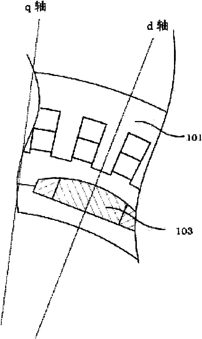
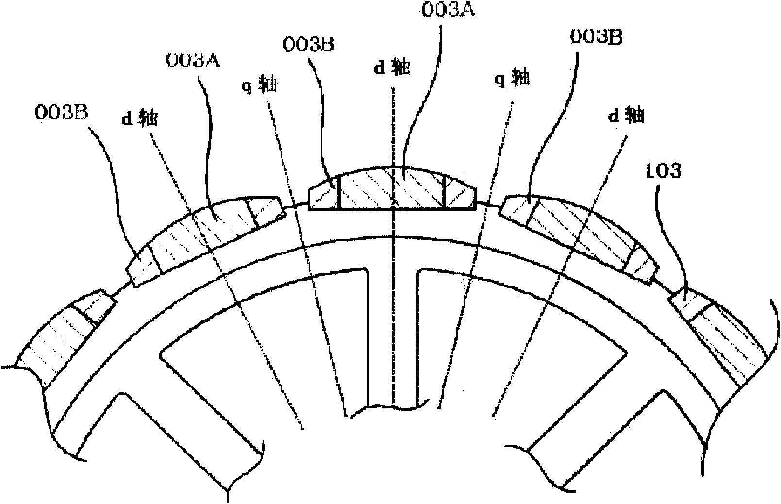
[0033] Such as figure 1 As shown, the permanent magnet generator 100 according to this embodiment has an armature part 101, an SPM rotor part 102, and a field permanent magnet 103 attached to the rotor part.

[0034] The armature unit 101 is an example of a generator armature structure, and an armature winding is wound around an armature core. When the field permanent magnet 103 rotates, an induced voltage is generated in the armature part 101 of the generator.

[0035] Formula 1

[0036] When the air gap magnetic flux density is Bg and the air gap area is Sg, then the total magnetic flux Φ is Φ=Bg·Sg. In addition, when the number of turns of the armature winding is W, the winding coefficien...

no. 2 Embodiment approach

[0067] Below, refer to Figure 5 , Figure 6 , the permanent magnet generator 200 and the rotor part 202 according to the second embodiment of the present invention will be described.

[0068] The permanent magnet generator 200 according to the second embodiment is different from the permanent magnet generator 100 according to the first embodiment in that it has an IPM rotor part 202 instead of the SPM rotor part 102 , and other configurations are the same. Therefore, in the following, for the sake of convenience of description, redundant description will be appropriately omitted, and the description will focus on points different from those of the first embodiment.

[0069] The IPM rotor part 202 is different from the SPM rotor part 102 in that the permanent magnets are not provided on the surface of the rotor, but are inserted and fixed in magnet insertion holes of a cylindrical rotor made of a ferromagnetic material.

[0070] The IPM rotor part 202 has a "salient pole eff...


PUM


Abstract

The invention discloses an excitation permanent magnet which is used on a rotor of a rotating electric machine, wherein more than two kinds of permanent magnets with different characteristics are combined, the excitation permanent magnet is divided into more than three parts along the width direction, a high coercive force permanent magnet A is used within a range which takes the central axis (i.e. d axis) of the excitation permanent magnet as a center, as for the part which is deviated outward from the d axis, a permanent magnet B group which has low coercive force and high residual flux density compared with the permanent magnet A is used. The mixed magnet of two magnets which have different using characteristics is taken as the excitation permanent magnet, the input amount of the high-priced and coercive force magnets is reduced, so the cost is reduced, and resources are protected.

Description

technical field [0001] The present invention relates to a field permanent magnet used in a rotating electric machine and the like, and a rotor or generator for a rotating electric machine using the field permanent magnet. Background technique [0002] In order to generate a high field magnetic flux, permanent magnet generators currently use expensive and high-performance rare-earth permanent magnets. [0003] In the non-patent literature, Komeiden Times 2010-No.3 "Development of PMG for wind power generation", a paper is published that discusses the impact of armature reaction on permanent The influence of magnets. [0004] This paper states that the largest armature reaction occurs when the control of the inverter is lost and a short-circuit current flows. At this time, the -Id current flows at the position of the q-axis (axis between magnets). Therefore, as a countermeasure, It is necessary to design the thickness of the magnet at the portion centered on the q-axis so as...

Claims


Application Information

Patent Timeline
IPC IPC(8): H02K1/06H02K1/27H01F7/02
CPCH02K1/278H02K1/2781
Inventor 宫本恭祐森下大辅林喜峰丁开鸿彭众杰吕思晶
Owner YASKAWA DENKI KK
Why Eureka
Try Eureka