Small-range magnetic conductance harmonic type magnetic gear pair of radial magnetic field

A radial magnetic field and magnetic gear technology, applied in the direction of electromechanical devices, electric vehicles, electrical components, etc., can solve the problems of complex output mechanism, increase bearing radial and axial load, limit application range, etc.

Inactive Publication Date: 2012-07-25
余虹锦
View PDF8 Cites 11 Cited by
  • Summary
  • Abstract
  • Description
  • Claims
  • Application Information

AI Technical Summary

Problems solved by technology

[0004] Recently, one of the inventors of this case has also proposed a new type of eccentric magnetic gear pair (201110277432.3, 201120350893.4 and 201110355864.1, 201120444409.4) with a new type of transverse and radial magnetic field magnetic field coupling type eccentricity. Two kinds of permanent magnetic fields with different numbers of poles interact and couple each other to achieve the purpose of torque transmission and variable speed transmission. However, the concept of double permanent magnetic coupling variable speed with less pole difference must adopt eccentricity in its structure, and rare earth materials The strong permanent magnetic field increases the radial and axial load of the bearing, and the output mechanism is complicated and inefficient due to eccentricity, and the process also increases the difficulty of processing and assembly. What is more unbearable is the rigid vibration of the system caused by the eccentric structure, which is difficult Adapt to the high-speed operation of the reduction mechanism, which limits its application range
So far, no one at home and abroad has proposed to improve the eccentric structure of the magnetic gear pair with less range by using the principle of less range and combining the principle of mechanical harmonic gear transmission technology. Such technical research and structural invention are of great importance to engineering applications. practical significance

Method used


Image

  • Small-range magnetic conductance harmonic type magnetic gear pair of radial magnetic field
  • Small-range magnetic conductance harmonic type magnetic gear pair of radial magnetic field
  • Small-range magnetic conductance harmonic type magnetic gear pair of radial magnetic field

Examples


Embodiment Construction

[0032] Below in conjunction with accompanying drawing and specific embodiment, the present invention will be further described:

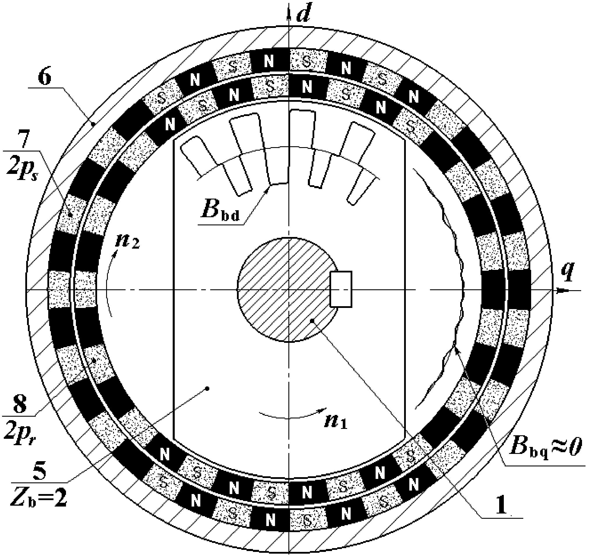
[0033] One, from image 3 , Figure 4 It can be seen that the working principle of the radial magnetic field with less pole-difference permeance harmonic wave magnetic gear pair is as follows: when working, the input shaft 1 drives the salient pole magnetic guide wave rotor 5 to rotate around the axis at high speed, driving the salient pole direct axis d direction The stator permanent magnet 7 and the rotor permanent magnet 8 are based on the principle of mutual attraction and coupling of opposite polarities, and according to the direct-axis air-gap magnetic density wave B in the direction of the d-axis bd Automatically arranged and integrated to form the attraction state of the heteropolar magnetic coupling with the largest salient pole magnetic permeability in the d-axis direction, the highest direct-axis magnetic density, and the strongest attra...


PUM


Abstract

The invention provides a small-range magnetic conductance harmonic type magnetic gear pair of a radial magnetic field. The magnetic gear pair can be widely applied to such industrial transmission fields as wind power generation, electric automobiles, ship drive and the like. The magnetic gear pair is characterized in that the magnetic gear pair comprises a permanently magnetic stator consisting of a stator core 6 and 2ps stator permanent magnets 7, a permanently magnetic rotor provided with 2pr rotor permanent magnets 8 and a salient pole type permeance wave rotor 5 with Zb salient pole waves; the numbers of pole pairs ps and pr are small in difference, and the pole pairs ps and pr are relatively prime; the permanently magnetic stator, the permanently magnetic rotor and the salient pole type permeance wave rotor 5 are coaxially mounted, and coupled with each other by a radial air-gap field; the permanently magnetic stator, and the permanently magnetic rotor and the salient pole type permeance wave rotor 5 are coupled in a salient pole direct-axis area of the salient pole type permeance wave rotor 5 which is rotated at the high speed based on the principle of attracting of a small-range heteropolarity magnetic field, so that the small-range magnetic gear pair is driven to rotate at the low speed, and the power transmission under the variable speed and torque can be achieved without mechanical touch and friction.

Description

technical field [0001] The present invention is a radial magnetic field with less pole-difference permeance harmonic magnetic gear pair, which utilizes the magnetic permeance alternating harmonic-type magnetic gear transmission technology constructed on the principle of less pole difference to realize high-speed, small-torque mechanical energy and low The variable speed transmission device with mutual conversion of speed and high torque mechanical energy can directly replace the conventional mechanical harmonic gear transmission transmission system, and is widely used in industrial robot servo drives, wind power generation, hydropower generation, electric vehicles, ship drives and other direct drives. in the field of industrial transmission. Background technique [0002] In many transmission fields of industrial applications, it is often necessary to realize the mutual conversion of low-speed, high-torque mechanical energy and high-speed, low-torque mechanical energy. High-...

Claims


Application Information

Patent Timeline
Patent Type & Authority Applications(China)
IPC IPC(8): H02K51/00H02K49/00
CPCY02T10/641Y02T10/64
Inventor 卢敏胡捷余虹锦
Owner 余虹锦
Why Eureka
Try Eureka