LED (Light-Emitting Diode) illumination dimming device

A technology for LED lighting and dimming devices, applied in lighting devices, light sources, electric light sources, etc., can solve the problems of large power supply and difficult layout and wiring of LED lamp beads, and achieve mature application technology, improve power supply utilization, and circuit work. Stable and reliable effect

Inactive Publication Date: 2012-07-25
SICHUAN SUNFOR LIGHT
View PDF6 Cites 23 Cited by
  • Summary
  • Abstract
  • Description
  • Claims
  • Application Information

AI Technical Summary

Problems solved by technology

[0006] The problem solved by the present invention is to solve the problem of large power supply and difficult layout and wiring of LED lamp beads in the prior art, and proposes a power supply method that uses H bridge to supply power to LED light source modules, only one power supply is needed Meet the power supply requirements of different color temperature units in the LED light source module, reduce the volume of the power supply by half, improve the power utilization rate, and the LED lighting dimming device with simple layout and wiring

Method used


Image

  • LED (Light-Emitting Diode) illumination dimming device
  • LED (Light-Emitting Diode) illumination dimming device
  • LED (Light-Emitting Diode) illumination dimming device

Examples


Embodiment 1

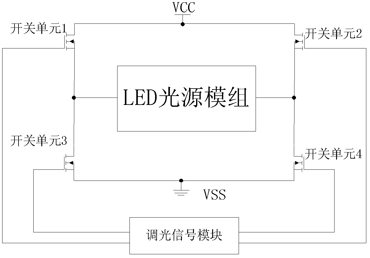
[0043] see Figure 6 , is the schematic diagram of the basic application circuit of the present invention. The control signals PWM1 and PWM2 are output by the control system. When the control signal PWM1 is at a high level, the control signal PWM2 is at a low level, and the control signal PWM1 controls the conduction of the MOS transistor Q1 and the MOS transistor Q4. , the high color temperature LEDC emits light; when the control signal PWM2 is at a high level, the control signal PWM1 is at a low level, and the control signal PWM2 turns on the MOS transistor Q2 and the MOS transistor Q3, and the low color temperature LEDW emits light. When the frequency of PWM1 and PWM2 is high enough, the light with high color temperature and low color temperature emitted by the LED will be mixed into a color temperature between high color temperature and low color temperature. By changing the high level time of PWM1 and PWM2, the color temperature can be achieved. adjustment.

Embodiment 2

[0045] see Figure 7 , is a preferred application circuit schematic diagram of the present invention, the control signals PWM1 and PWM2 are output by the control system, when the control signal PWM1 is at a high level, the control signal PWM2 is at a low level, and the control signal PWM1 controls the conduction of the MOS transistor Q1 to control The signal PWM1 reverses through the reverse gate B1 to turn off the MOS transistor Q3, the control signal PWM2 controls the MOS transistor Q2 to turn off, the control signal PWM2 passes through the reverse gate to turn on the MOS transistor Q4, the current flows through the MOS transistor Q1, and flows through the high The color temperature LEDC returns to the VSS terminal through the MOS tube Q4, and the high color temperature LEDW emits light; when the control signal PWM2 is at a high level, the control signal PWM1 is at a low level, and the control signal PWM2 controls the conduction of the MOS tube Q2, and the control signal PWM2...

Embodiment 3

[0047] see Figure 8 , is another preferred application circuit schematic diagram of the present invention, the control signal PWM is output by the control system, when the control signal PWM is at a high level, the MOS transistor Q1 is turned on, and the control signal turns off the MOS transistor Q3 through the reverse gate B1, The control signal passes through the reverse gate B3 to turn off the MOS tube Q2, the control signal passes through the reverse gate B3 and then through the reverse gate B2 to turn on the MOS tube Q4, the current flows through the MOS tube Q1, flows through the high color temperature LEDC, and passes through the MOS tube Q4, back to the VSS terminal, the high color temperature LEDC emits light; when the control signal PWM is low, the MOS transistor Q1 is turned off, the control signal passes through the reverse gate B1 to turn on the MOS transistor Q3, and the control signal passes through the reverse gate B3 to make the MOS transistor Q4 turn on. Th...


PUM


Abstract

The invention relates to the technology of a switch power supply and an electronic circuit, in particular to an LED (Light-Emitting Diode) illumination dimming device, which supplies power to an LED light supply module through an H-bridge type circuit and uses matrix net-type wiring for the LED light supply module. According to the main technical scheme, the H-bridge type circuit consists of four switch units; the LED light supply module is used as a load of a common bridge arm; and a power supply module is connected with the both ends of an H bridge, so as to realize cross power supply of the LED light supply module. The LED illumination dimming device has the beneficial effects as follows: the power supply of the LED illumination device is realized in a power supply manner of the H bridge, and the functions of the former two power supplies can be realized by only using one power supply, so that the quantity of the power supplies is reduced by 50% and the energy is greatly saved; and meanwhile, the matrix net-type wiring of LED lamp bulbs can be realized, so that the wiring layout of the LED light supply module is simpler, easier and more reliable. Therefore, the production and installation process of the LED illumination device can be greatly simplified, and the cost can be effectively reduced. The LED illumination dimming device is particularly applicable to the LED illumination device with various color temperatures.

Description

technical field [0001] The invention relates to a switching power supply and an electronic circuit technology, in particular to an LED lighting dimming device that supplies power to an LED light source module through an H-bridge circuit and adopts matrix network wiring for the LED light source module. Background technique [0002] Connect two of the four switching tubes, and connect the other two switching tubes and connect them through a common line. Because of this connection and the load on the public line, it often looks like an H when drawn, so it is The name H bridge, the four switch tubes are usually called bridge arms, and the common line in the middle is usually called a common bridge arm. The H-bridge circuit can be in the same circuit, so that the bridge arms on both sides always maintain the opposite output, so that the polarity of the load can be reversed in the case of a single power supply to meet the needs of motor drive and other aspects. [0003] As a high...

Claims


Application Information

Patent Timeline
Patent Type & Authority Applications(China)
IPC IPC(8): H05B37/02
Inventor 封正勇龙文涛杨冕李东明
Owner SICHUAN SUNFOR LIGHT
Why Eureka
Try Eureka