
Municipal refuse treatment device and method

A municipal waste and treatment device technology, which is applied in the field of waste recycling, can solve problems such as lower calorific value, high energy consumption, and deterioration of combustion characteristics, and achieve the effects of reducing heat load, reducing COD, and reducing pressure

Inactive Publication Date: 2012-08-01
苏州天荣能源环境科技有限公司
View PDF8 Cites 12 Cited by
  • Summary
  • Abstract
  • Description
  • Claims
  • Application Information

AI Technical Summary

Problems solved by technology

[0008] However, there are still some problems to be improved in the conversion of municipal waste into RDF: 1) Many processes do not consider the drying of RDF. If the water content in RDF is too high, the calorific value will be directly reduced, and even the combustion characteristics will deteriorate sharply; or , the conventional drying method used in some processes consumes a lot of energy. For example, in the production experiment of the Institute of Engineering Thermophysics of the Chinese Academy of Sciences, the drying accounted for more than half of the cost of drying. Japan uses kerosene to burn and dry RDF in RDF production. It takes 1 ton of garbage to process It consumes 56kg of kerosene. If direct combustion of RDF is used for drying, the RDF loss will reach 10%~15%; 2) Most of the permeate treatment only considers the removal of its polluting components, but does not consider the reuse of permeate

Method used


Image

  • Municipal refuse treatment device and method
  • Municipal refuse treatment device and method
  • Municipal refuse treatment device and method

Examples


Embodiment Construction

[0039] The present invention will be described in detail below with reference to the accompanying drawings and in combination with embodiments.

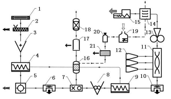
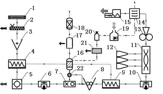
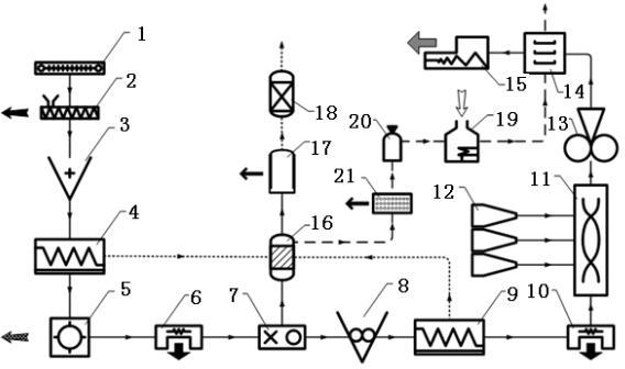
[0040] seefigure 1 Shown, a kind of municipal waste disposal device comprises feeder 1, screening machine 7, mixer 11, RDF molding machine 13, drier 14, RDF packing machine 15, anaerobic generator 16 and biogas boiler 19, described feeding Between the discharge port of the material machine 1 and the feed port of the RDF subpacker 15, the primary separator 2, the coarse crusher 3, the primary dehydrator 4, the winnowing machine 5, and a The primary metal separator 6, the screening machine 7, the fine crusher 8, the secondary dehydrator 9, the secondary metal separator 10, the mixer 11, the RDF forming machine 13 and the dryer 14; The organic material discharge port of the screening machine 7 is connected with the feed port of the anaerobic generator 16 through a pipeline, and the discharge port of the anaerobic generator 16 is connect...


PUM

PropertyMeasurementUnit
Diameteraaaaaaaaaa
Lengthaaaaaaaaaa

Abstract

The invention discloses a municipal refuse treatment device and a municipal refuse treatment method. A primary selection machine, a coarse crusher, a primary dehydrator, a winnowing machine, a primary metal sorting machine, a screening machine, a fine crusher, a secondary dehydrator, a secondary metal sorting machine, a mixer, a refuse derived fuel (RDF) molding machine and a drying machine are sequentially connected in series between a feeder and an RDF racking machine, wherein the screening machine is connected with an anaerobic generator; a stable dehydrator is connected in series between the anaerobic generator and a biochemical treater; the bottoms of the primary dehydrator and the second dehydrator are provided with water outlets, and the water outlets are connected with a water inlet of the anaerobic generator through a pipeline; and a methane purifier, a gas storage tank and a methane boiler are sequentially connected in series between the anaerobic generator and hot air of the drying machine. Due to a two-stage dehydration mode, a thermal load of the drying machine is effectively reduced before refuse enters the drying machine, and the consumption of external energy is effectively reduced; and moreover, in the process of anaerobic reaction, the chemical oxygen demand (COD) of the effluent is reduced, and the pressure of a subsequent biochemical reactor is reduced.

Description

technical field [0001] The invention belongs to the technical field of garbage recycling, and relates to a garbage treatment device and method, in particular to a device and method for converting municipal garbage into garbage-derived fuel. Background technique [0002] In 2008, about 155 million tons of urban domestic garbage were collected and transported in my country, and about 70 million tons of domestic garbage were collected in counties and towns. Urban domestic waste is increasing rapidly at an average annual rate of 4-8%. Garbage besieged cities have become the status quo in most cities in my country. The accumulation of urban domestic waste occupies a large amount of land and causes serious environmental pollution; realize its harmlessness and reduction It is imminent to transform and recycle resources. [0003] At present, the common treatment methods of municipal solid waste include the following: [0004] Landfill method: This is the main treatment method curre...

Claims


Application Information

Patent Timeline
IPC IPC(8): B09B3/00B09B5/00
CPCY02W30/20
Inventor 冯诗愚高秀峰侯雄坡齐宝金
Owner 苏州天荣能源环境科技有限公司
Learn More