Process and die for one-time round-bending and molding

A technology for forming molds and concave molds, applied in the field of stamping, can solve problems such as complex processes, and achieve the effects of good forming effect, low cost, and halving of the process.

Inactive Publication Date: 2012-08-01
无锡华尔斯科技有限公司
8 Cites 16 Cited by

AI-Extracted Technical Summary

Problems solved by technology

[0003] Aiming at the shortcomings of the above-mentioned three-step forming method in the production of large-diameter cylindrical parts, the applicant provides...

Abstract

The invention discloses a process and a die for one-time round-bending and molding. The die comprises an upper female die, a core rod, a lower female die, a feeding mechanism, a material pressing mechanism and a discharging mechanism, wherein the upper female die is fixed to an upper template and slides up and down on a die set through a guide sleeve which is matched with a vertical guide column; the lower female die is fixed to a lower template; the core rod is fixed to a vertical lateral sliding plate capable of moving up and down and is positioned between the upper female die and the lower female die; and a horizontal guide column is provided with a horizontal lateral sliding plate, and the horizontal lateral sliding plate is connected with a front handle through a pull rod. Compared with the conventional molding process, the process for one-time round-bending and molding has the advantages that the procedures are reduced by a half, the structure is compact and reasonable, equipment, manpower and sites are greatly reduced, the energy resources are saved, the cost is low, the molding effect of large rings is good, the quality performance is stable, and the process and the die have higher cost performance and high economic benefit.

Application Domain

Technology Topic

Image

  • Process and die for one-time round-bending and molding
  • Process and die for one-time round-bending and molding
  • Process and die for one-time round-bending and molding

Examples

  • Experimental program(1)

Example Embodiment

[0015] The specific embodiments of the present invention will be described below in conjunction with the drawings.
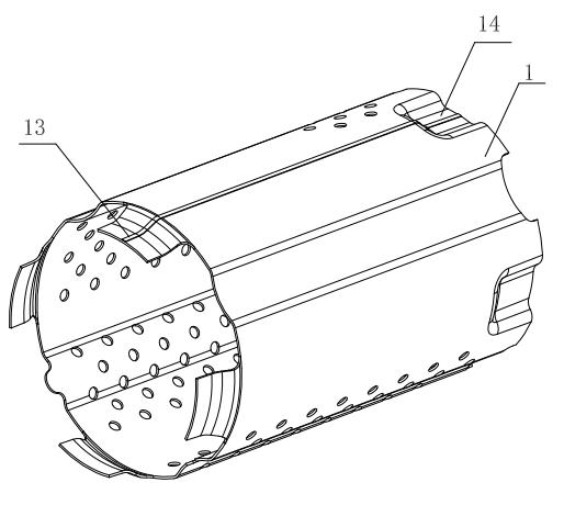
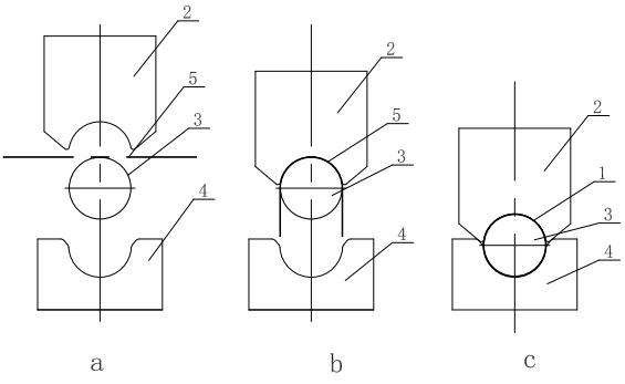
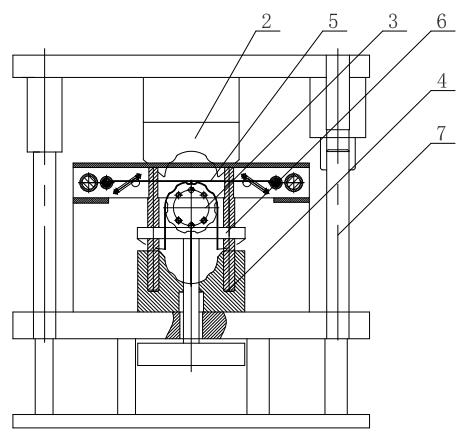
[0016] Such as figure 2 As shown, the one-shot round forming process of the present invention is formed by a single set of molds at one time, and the blanked sheet 5 is placed horizontally between the upper die 2 and the core rod 3 (see figure 2 a), the upper die 2 goes down to bend the two edges of the sheet 5 into a vertical state. When the upper die 2 is in place, the cavity between the upper die 2 and the core rod 3 forms the upper semicircle of the workpiece 1 (see figure 2 b); Then the upper die 2 and the core rod 3 go down at the same time, the two edges of the sheet 5 touch the arc surface of the lower die 4, are gradually closed and finally formed in the cavity between the lower die 4 and the core rod 3 Out the lower semicircle of workpiece 1 (see figure 2 c). At this time, the ring workpiece 1 is reshaped by adjusting the pressure of the main cylinder and the lower top cylinder of the hydraulic press and the pressure holding time.
[0017] Such as Figure 3 to Figure 5 As shown, the one-shot round forming mold of the present invention is composed of an upper die 2, a core rod 3, a lower die 4, a feeding mechanism, a pressing mechanism, and a discharging mechanism. The upper die 2 is fixed on the upper template, and slides on the mold base through the guide sleeve matched with the vertical guide post 7, the lower die 4 is fixed on the lower template, and the core rod 3 is fixed on the vertical side that can move up and down The sliding plate 9 is located between the upper die 2 and the lower die 4. The horizontal guide post 8 is provided with a horizontal side sliding plate 11 which is connected with the handle 10 on the front side through a pull rod 12.
[0018] In actual work, the punch of the hydraulic press moves down, driving the upper template and the upper die 2 down. At this time, the ejector cylinder at the bottom of the top plate 6 is provided with a certain hydraulic pressure to support the mandrel 3, and the upper die 2 overcomes The deformation force of the sheet 5 is pressed to form an upper semicircle. Then the punch continues to descend. At this time, the punching pressure of the main cylinder of the hydraulic press is greater than the hydraulic pressure of the ejector cylinder, so that the upper die 2 and the core rod 3 go down together, and the two vertical edges of the sheet 5 enter the lower die 4 and form the lower die. semicircle. At this time, by adjusting the pressure of the main cylinder of the hydraulic press, the pressure of the lower top cylinder and the pressure holding time (the pressure holding time is generally 3±1 seconds), the ring shaping action is completed. This forming action can be completed at the same time figure 1 To form the inner boss 14 of the middle workpiece 1, the outer boss 13 needs another mold to complete.
[0019] After the forming action is completed, the main cylinder exits, the top cylinder exits, hold the handle 10 with your hand and pull it outwards. At this time, the horizontal side slide 11 will move outward with the handle 10, and when the horizontal side slide 11 moves to the outermost limit position , Take out the workpiece 1 from the mandrel 3 by hand to complete the part unloading process.
[0020] The above description is an explanation of the present invention, not a limitation of the present invention. For the scope of the present invention, please refer to the claims. The present invention may be modified in any form without departing from the spirit of the present invention.

PUM

no PUM

Description & Claims & Application Information

We can also present the details of the Description, Claims and Application information to help users get a comprehensive understanding of the technical details of the patent, such as background art, summary of invention, brief description of drawings, description of embodiments, and other original content. On the other hand, users can also determine the specific scope of protection of the technology through the list of claims; as well as understand the changes in the life cycle of the technology with the presentation of the patent timeline. Login to view more.

Similar technology patents

Electron gun

Owner:INST OF FLUID PHYSICS CHINA ACAD OF ENG PHYSICS

Classification and recommendation of technical efficacy words

Why Eureka
Try Eureka