Thin-wall deep diving pontoon capable of automatically realizing internal and external pressure balance

A technology of internal and external pressure and floating tanks, which is applied to underwater operation equipment, transportation and packaging, ships, etc., and can solve problems such as increasing structural strength, reducing net buoyancy, and losing the buoyancy function

Active Publication Date: 2012-08-01
GUANGZHOU INST OF ENERGY CONVERSION - CHINESE ACAD OF SCI
View PDF4 Cites 5 Cited by
  • Summary
  • Abstract
  • Description
  • Claims
  • Application Information

AI Technical Summary

Problems solved by technology

[0003] At present, most of the rigid floating tanks used in the field of ocean engineering are airtight structures. When the airtight structure is used underwater, there are potential safety hazards. The external pressure of the airtight structure increases with the increase of water depth. When the water pressure exceeds the pressure limit of the structure itself, the airtight structure will be damaged by the external water pressure, the structure will be damaged, seawater will enter the cavity, the buoyancy of the buoyancy tank will be lost, and the buoyancy aid function will be lost
[0004] Therefore, in order to avoid being crushed at a greater depth, the structure of ...

Method used


Image

  • Thin-wall deep diving pontoon capable of automatically realizing internal and external pressure balance
  • Thin-wall deep diving pontoon capable of automatically realizing internal and external pressure balance
  • Thin-wall deep diving pontoon capable of automatically realizing internal and external pressure balance

Examples


Embodiment Construction

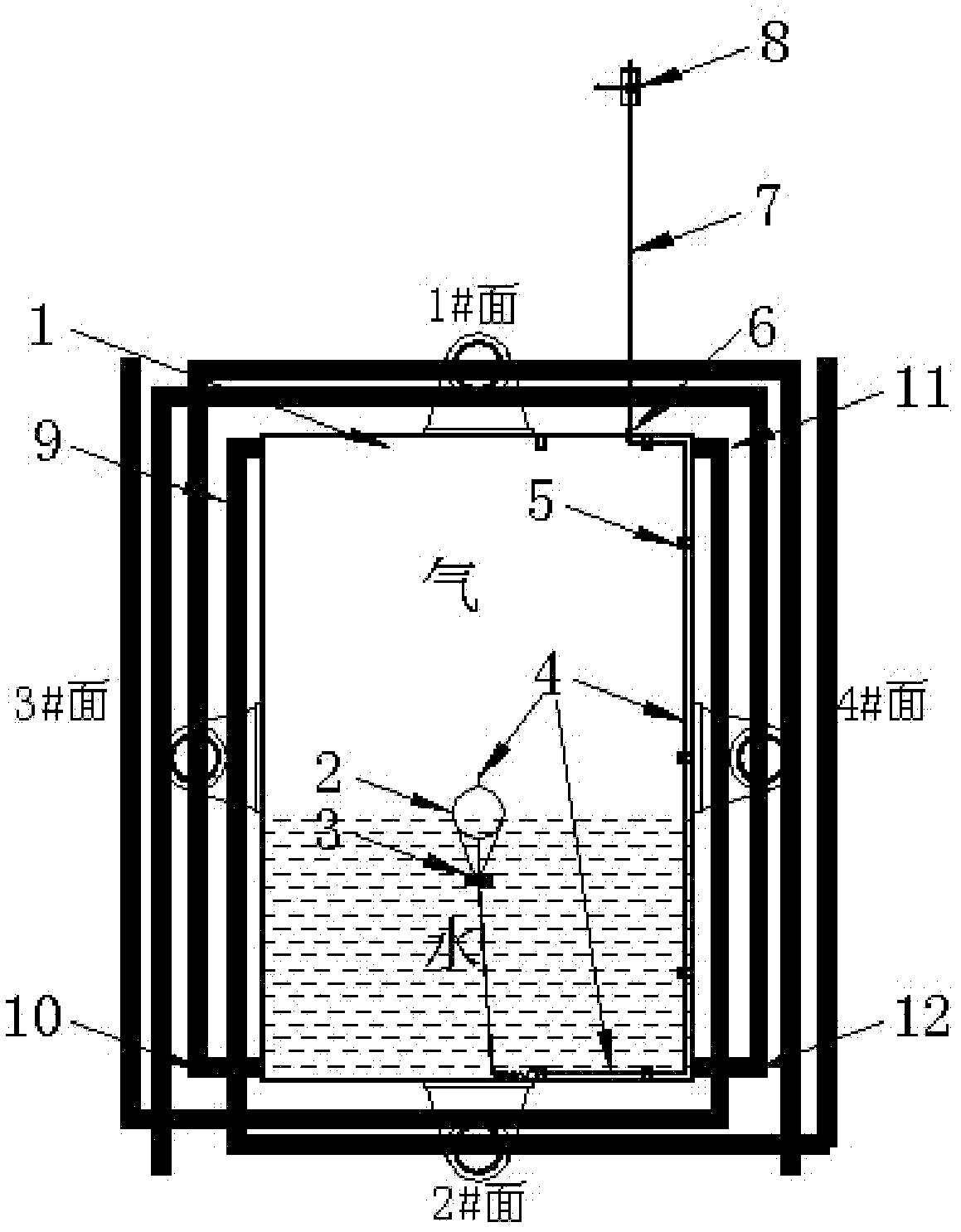
[0026] The thin-walled deep-submersible buoyant tank of the present invention can be designed into any shape according to needs, but its basic composition and working principle are the same. Firstly, the structure introduction and function description will be given by taking the square buoy working under two-dimensional conditions as an example.

[0027] Such as figure 1 As shown, the four faces of the buoyancy tank main body 1 are shown in the figure as side 1#, side 2#, side 3# and side 4#, and these 4 faces can be installed with lugs 13 as required, so as to facilitate the integration with other needs. Structural connections to aid buoyancy. Floating ball 2 is placed inside the main body of the buoyancy tank 1, and the weight 3 is fixedly connected to the bottom of the buoyant ball 2. The gravity of the weight 3 is less than the buoyancy of the buoyant ball 2 in the water. 3 Pull down the floating ball 2, and the buoyancy of the floating ball 2 is greater than the gravity ...


PUM


Abstract

The invention relates to a thin-wall deep diving pontoon capable of automatically realizing internal and external pressure balance. The pontoon comprises a pontoon main body, lifting lugs, external water pipes, a floating ball, a weight, an internal gas pipe, pipe clamps, a gas pipe joint, an external gas pipe and a ball valve, wherein the external water pipes are arranged on the outer walls of the four sides of the pontoon main body, are continuously arranged along the side lines of the outer walls of the pontoon and pass through all corners; the lifting lugs are arranged on the outer walls of the four sides of the pontoon main body; the weight is fixedly connected below the floating ball and arranged in the pontoon; the internal gas pipe is fixed between the upper end of the floating ball and the weight; the port of the gas pipe on the floating ball is open; the internal gas pipe with enough length is arranged in the pontoon, so that the floating ball and the weight can arrive in any place in the pontoon; the internal gas pipe extends to the inner port of the gas pipe joint along the inner wall of one side of the pontoon main body through the pipe clamps; the gas pipe joint crosses one side wall of the pontoon main body, and a junction is sealed by welding; one end of each external water pipe is connected to the outer port of the gas pipe joint; and the ball valve is arranged at the other end of each external gas pipe.

Description

technical field [0001] The invention relates to a buoyant tank, in particular to a thin-walled deep submersible buoyant tank which automatically realizes internal and external pressure balance. Background technique [0002] In the field of marine engineering, buoyancy tanks or buoyancy chambers are widely used in various marine devices and structures. For example, a device floating in the ocean must have a built-in or external buoyancy tank or buoyancy chamber of sufficient volume to provide buoyancy to the device, so that the device can float in the ocean stably and for a long time; Use buoyancy tanks or buoyancy chambers to provide buoyancy for sunken ships or other devices sunk on the seabed, and float the submarine ships or devices out of the seabed; there are also other temporary water projects such as pontoon bridges and floating docks that also use buoyancy tanks to provide buoyancy. [0003] At present, most of the rigid floating tanks used in the field of ocean eng...

Claims


Application Information

Patent Timeline
IPC IPC(8): B63C11/00
Inventor 游亚戈盛松伟王坤林吝红军叶寅
Owner GUANGZHOU INST OF ENERGY CONVERSION - CHINESE ACAD OF SCI
Why Eureka
Try Eureka