Hydraulic transmission device allowing the recovery of energy

A technology of hydraulic transmission device and hydraulic pump, which is applied in the direction of transmission device control, accumulator device, fluid pressure actuation device, etc. It can solve the problems of high cost, complex device, high energy, etc., and achieve simple structure and high energy efficiency effect

Inactive Publication Date: 2012-08-01
POCLAIN HYDRAULICS IND
View PDF9 Cites 23 Cited by
  • Summary
  • Abstract
  • Description
  • Claims
  • Application Information

AI Technical Summary

Problems solved by technology

[0007] The downside of this setup is that it uses a lot of energy in the form of heat every stop period and also has to use a larger

Method used


Image

  • Hydraulic transmission device allowing the recovery of energy
  • Hydraulic transmission device allowing the recovery of energy
  • Hydraulic transmission device allowing the recovery of energy

Examples


Embodiment Construction

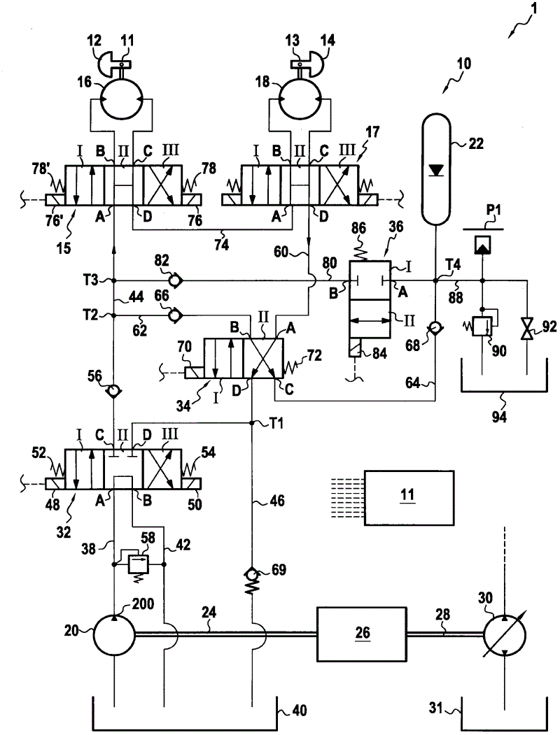
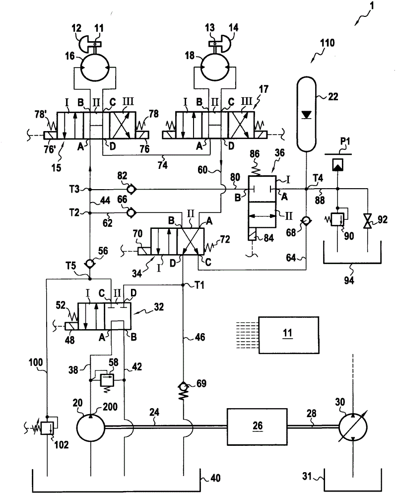
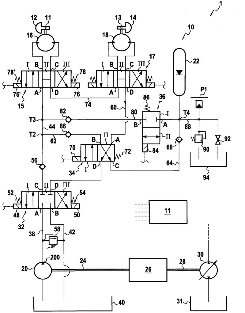
[0083] will now combine figure 1 The hydraulic transmission device 10 according to the present invention in the first embodiment is described.

[0084] The device 10 is a device for driving two eccentric masses 12 and 14 . These eccentric masses or "vibrating masses" are attached to the inside of two pressure rollers arranged respectively at the front and rear of the roller (not shown). These eccentric masses are attached eccentrically to the shafts 11 and 13 of the two press rollers, respectively, so that when the eccentric masses are actuated to rotate about the axes 11 and 13, they can vibrate the press rollers.

[0085]The device 10 associated with the shafts 11 , 13 and the masses 12 , 14 constitutes the assembly 1 according to the invention.

[0086] Device 10 includes:

[0087] Two radial piston hydraulic motors 16 and 18;

[0088] a hydraulic pump 20;

[0089] a fluid accumulator 22 capable of storing and delivering fluid under pressure; and

[0090] A control u...


PUM


Abstract

The device (10) has a fluid accumulator (22) to store and deliver pressurized fluid. A hydraulic motor (16) acts as a hydraulic pump (20) conveying the fluid in the accumulator in an energy recovery mode. The motor is driven by the fluid delivered by the pump in a driving mode. The pump supplies the motor with the fluid collected from a high-pressure-less reservoir in the driving mode. The motor is supplied with the fluid by the pump withdrawing the fluid from the reservoir in the energy recovery mode. An independent claim is also included for an assembly comprising a transmission device, a shaft and a mass.

Description

technical field [0001] The present invention relates to a hydraulic transmission capable of driving in rotation and braking one or more rotating elements; these elements need to be driven in rotation and then braked several times. [0002] In particular, the present invention contemplates a device for rotating a plurality of eccentric masses, so called because they are mounted eccentrically on the shaft of a roll of a road roller . When these eccentric masses are actuated to rotate about these axes, the eccentric masses vibrate the pressure rollers of the road roller, which can compact the road surface under construction. The required rotational speed is quite high, usually varying between 2000 and 4200 rpm. [0003] In order to meet the requirements of the compaction quality, when the roller advances, it receives a specified number of impacts per meter of road surface (corresponding to the rotation performed by the eccentric mass body). Therefore, depending on the speed ch...

Claims


Application Information

Patent Timeline
IPC IPC(8): F15B21/14F15B1/02
CPCY02T10/6208F15B21/14F15B1/027F15B1/024F16H61/4148F16H61/4096B60K6/12Y02T10/62
Inventor 让·赫伦
Owner POCLAIN HYDRAULICS IND
Why Eureka
Try Eureka