Self-aligning roller bearing for main shaft of wind turbine generator and design method thereof

A technology for spherical roller bearings and wind power generators, which is applied in the direction of roller bearings, shafts and bearings, rolling contact bearings, etc., and can solve problems affecting the service life of the unit, wear of the raceways, unbalanced force on the rollers, etc.

Active Publication Date: 2012-08-01
CRRC WIND POWER(SHANDONG) CO LTD
View PDF7 Cites 5 Cited by
  • Summary
  • Abstract
  • Description
  • Claims
  • Application Information

AI Technical Summary

Problems solved by technology

Due to the design characteristics of the double-row spherical roller bearing itself, when the thrust is received in the upwind direction, the load on the rollers on the downwind side is much greater than that on the upwind side. According to field tests, the force difference between the two rows of rollers is at least 3 times, the force on the front and rear rollers is unbalanced, and the wear of the rear rollers and their raceways is serious, which seriously affects the service life of the unit

Method used


Image

  • Self-aligning roller bearing for main shaft of wind turbine generator and design method thereof
  • Self-aligning roller bearing for main shaft of wind turbine generator and design method thereof
  • Self-aligning roller bearing for main shaft of wind turbine generator and design method thereof

Examples


Embodiment Construction

[0020] The present invention will be further described below in conjunction with the accompanying drawings and embodiments.

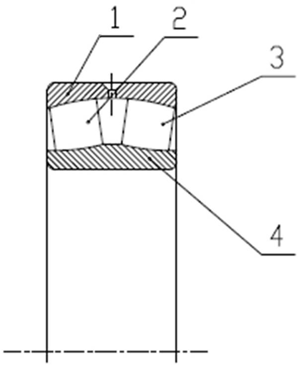
[0021] Such as figure 1 As shown, the structural schematic diagram of the existing spherical roller bearing for the main shaft of the wind power generator is given, which includes bearing outer ring 1, bearing inner ring 4, front roller 2, rear roller 3; front roller 2 and the diameter size of rear row roller 3 are equal. During use, due to the huge thrust of the wind rotor, the thrust load is entirely borne by the spherical roller bearing on the main shaft, so that the rollers on the downwind side are much more loaded than the upwind side. Generally, the force difference between the two rows of rollers (2, 3) is at least 3 times, the force of the front and rear rollers is unbalanced, and the wear of the rear roller 3 and its raceway is serious, which seriously affects the use of the unit. life.

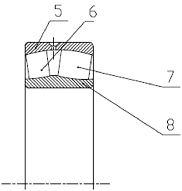
[0022] Such as figure 2 As shown, the structural sc...


PUM


Abstract

The invention relates to a self-aligning roller bearing for a main shaft of a wind turbine generator and a design method thereof. The self-aligning roller bearing comprises a bearing outer ring, a bearing inner ring and two rows of rollers; and the self-aligning roller bearing is characterized in that the length of one row of rollers close to a wind wheel side on the self-aligning roller bearing is smaller than that of the other row. The design method of the bearing comprises the steps of: a, establishing a coordinate system; b. calculating stress of the main shaft by utilizing a formula F1=1/2C<F>RhoV<2>; c, calculating stress of the self-aligning roller bearing; d-1, calculating contact stress; d-2, fetching a lower limit value; d-3, fetching an upper limit value; d-4, implementing the calculation by utilizing a difference method, and d-5, calculating a proportionality factor satisfying an absolute value of (U - V) is smaller than 3U/100 or an absolute value of (U - V) is smaller than 3V/100, and designing a bearing meeting the requirement. According to the bearing and a bearing calculation method, the contact stress between each roller and a raceway can be effectively reduced; and a finite element method and the difference method are adopted, so that the difference value between the contact stresses of the two rows of rollers can be controlled within 3 percent, thereby solving the unbalance stress problem of the roller, reducing the failure rate and improving the service life of the bearing.

Description

technical field [0001] The present invention relates to a self-aligning roller bearing for a main shaft of a wind power generator and a design method thereof, more specifically, to a self-aligning roller bearing for a main shaft of a wind power generator with two unequal rollers applied to a megawatt wind power unit Bearings and their design methods. Background technique [0002] Wind energy resources, as a clean renewable energy, widely exist all over the world. The resources are abundant, inexhaustible, and environmentally friendly. Therefore, wind power generation is safe and clean, and can provide long-term and stable energy supply for human beings. At present, major developed countries and developing countries have taken the development of wind power generation technology as a national policy and an important means to deal with energy challenges in the new century. [0003] The transmission chain is the core part of the wind turbine, and the main shaft bearing is the ...

Claims


Application Information

Patent Timeline
Patent Type & Authority Applications(China)
IPC IPC(8): F16C23/08F16C33/58F16C33/66F16C35/04
CPCF16C19/38F16C23/086F16C2240/40F16C2300/14F16C2360/31
Inventor 于良峰周传海吕超葛春丽李刚强
Owner CRRC WIND POWER(SHANDONG) CO LTD
Why Eureka
Try Eureka