
Backlight module and liquid crystal display device comprising same

A technology for backlight modules and light sources, which is applied to lighting devices, fixed lighting devices, components of lighting devices, etc., can solve problems such as the quality degradation of liquid crystal display devices and the formation of local light spots, and achieve the effect of solving the problem of light leakage and improving quality.

Inactive Publication Date: 2012-08-01
TCL CHINA STAR OPTOELECTRONICS TECH CO LTD
View PDF3 Cites 9 Cited by
  • Summary
  • Abstract
  • Description
  • Claims
  • Application Information

AI Technical Summary

Problems solved by technology

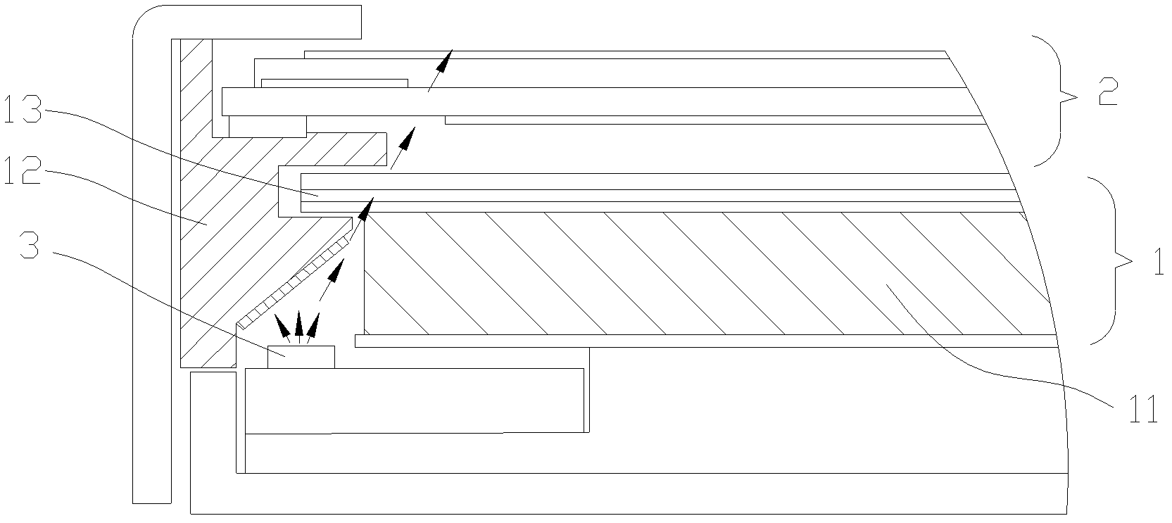
like figure 1 As shown, the liquid crystal display device mainly includes a backlight module 1 and a liquid crystal display panel 2. Here, the backlight module 1 is a side-light backlight module of a bottom-illuminated type, which is an important idea for designing a narrow-frame liquid crystal display device. , which can achieve a frame design with a minimum length of 4.3mm. Due to the thermal expansion and contraction of the light guide plate 11 during operation, and the manufacturing tolerance of the light guide plate 11, there will be a certain gap between the end surface of the light guide plate 11 and the middle frame 12. Assembling the gap, this will cause the problem of light leakage. The light from the light source 3 is directly emitted from the above-mentioned gap. Since the light is very bright, it will form a bright line at the frame of the liquid crystal display panel 2 after passing through the optical film 13. When the light leakage is serious, there will be May form local light spots, resulting in a decline in the quality of liquid crystal display devices

Method used


Image

  • Backlight module and liquid crystal display device comprising same
  • Backlight module and liquid crystal display device comprising same
  • Backlight module and liquid crystal display device comprising same

Examples


Embodiment Construction

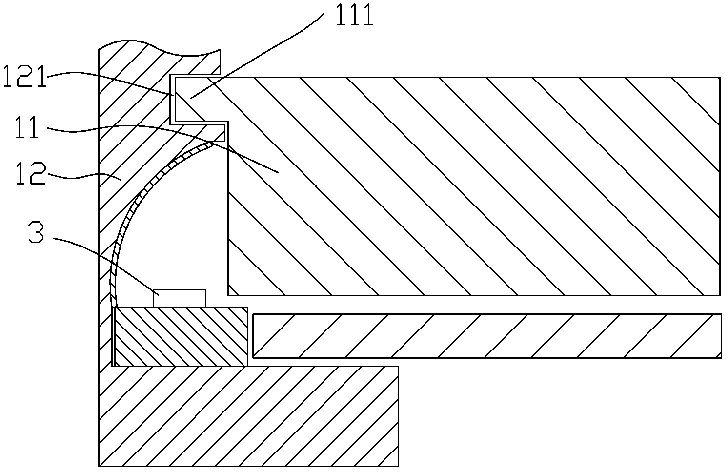
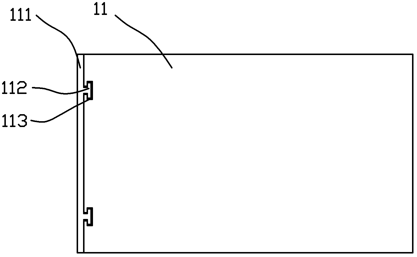
[0020] The present invention discloses a liquid crystal display device, including a backlight module, as Embodiment 1 of the backlight module of the present invention, such as figure 2 and image 3 As shown, the backlight module is a backlight module of the bottom surface light type, and the backlight module includes a middle frame 12, a light guide plate 11 and a light source 3. The shielding structure directly emitted from the gap between the light plates 11, the shielding structure includes a groove 121 arranged on the middle frame 12 and a lug 111 arranged on the light guide plate 11, and the lug 111 is arranged in the groove 121 . In this embodiment, the cross-sectional shape of the lug 111 is rectangular, and the shape of the lug 111 corresponds to that of the groove 121 , so that the matching structure of the lug 111 and the groove 121 has a positioning function. In order to completely block the light, the length of the lug is preferably greater than or equal to the ...


PUM


Abstract

The invention belongs to the field of liquid crystal display, and particularly relates to a backlight module and a liquid crystal display device comprising the same. The backlight module comprises a middle frame, a light guide plate and a light source, and is characterized by further comprising a shielding structure, the shielding structure prevents light of the light source from directly emitting out from a gap between the middle frame and the light guide plate and comprises a groove and a convex lug, the groove is arranged on the middle frame, and the convex lug is disposed on the light guide plate and arranged in the groove. Due to the shielding structure, the light cannot directly emit on an optical membrane from the gap between the middle frame and the light guide plate, the problem of light leakage is resolved, bright lines and light spots cannot appear on a liquid crystal display panel, and accordingly the quality of the liquid crystal device is improved.

Description

technical field [0001] The invention belongs to the field of liquid crystal display, and more specifically relates to a backlight module and a liquid crystal display device using the backlight module. Background technique [0002] Liquid crystal display devices have been widely used in recent years due to their advantages of low power consumption, low manufacturing cost and no radiation. Such as figure 1 As shown, the liquid crystal display device mainly includes a backlight module 1 and a liquid crystal display panel 2. Here, the backlight module 1 is a side-light backlight module of a bottom-illuminated type, which is an important idea for designing a narrow-frame liquid crystal display device. , which can achieve a frame design with a minimum length of 4.3mm. Due to the thermal expansion and contraction of the light guide plate 11 during operation, and the manufacturing tolerance of the light guide plate 11, there will be a certain gap between the end surface of the ligh...

Claims


Application Information

Patent Timeline
Patent Type & Authority Applications(China)
IPC IPC(8): F21S8/00F21V11/00F21V8/00G02F1/13357
CPCG02B6/0091G02F1/133615G02B6/0013G02B6/0031
Inventor 周革革黄建发
Owner TCL CHINA STAR OPTOELECTRONICS TECH CO LTD
Learn More