[0018] Typical embodiments embodying the features and advantages of the present invention will be described in detail in the following description. It should be understood that the present invention is capable of various changes in different embodiments without departing from the scope of the present invention, and that the description and drawings therein are illustrative in nature and not limiting. this invention.
[0019] The rock-soil rheological test method is to simulate different stress field environments of the rock and soil by applying pressure to the rock-soil test pieces set in the pressure chamber, and then by detecting the change parameters of the rock-soil test pieces in the above-mentioned environment to simulate the actual rock-soil Evaluation of soil changes under different stress field environments. In the present invention, the axial pressure and radial pressure of the rock-soil test piece located in the pressure chamber are absolutely isolated, so that the axial pressure and the radial pressure are independent of each other. When the radial pressure of the rock and soil specimen is greater than the axial pressure, it can be used to simulate the stress field of the actual rock and soil when it is under tension. The changing parameters of rock and soil specimens include stress, strain, lateral pressure and temperature, and the strain includes axial strain and radial strain.
[0020] In addition, the rock and soil test piece can also be heated through the pressure chamber to simulate different temperature environments of the actual rock and soil. Furthermore, in order to save test time, the number of rock-soil test pieces and pressure chambers is the same, both are more than 2, and each rock-soil test piece is tested at the same time. In this embodiment, there are 5 rock-soil test pieces and 5 pressure chambers.
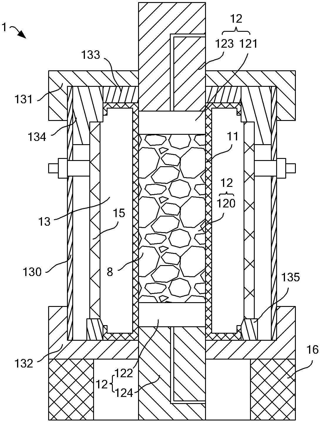
[0021] figure 1 Shown is the structure of the pressure chamber 1 in this embodiment. The pressure chamber 1 comprises an axial pressure chamber 12 and an annular pressure chamber 13 . The axial pressure chamber 12 includes an upper pressure chamber 121 , a specimen chamber 120 and a lower pressure chamber 122 . In this embodiment, the geotechnical test piece 8 can be selected from geological materials such as coal mines or other mine soft rocks, and the geotechnical test piece 8 is installed in the test piece chamber 120 . The annular pressure chamber 13 is a sealed oil bag filled with pressure-adjustable oil, and the upper pressure chamber 121 and the lower pressure chamber 122 are pads for adjusting the pressure through the oil. Wherein, the annular pressure chamber 13 is an annular cylinder surrounding the axial pressure chamber 12 radially. like Figure 4 As shown, the annular pressure chamber 13 is connected to the energy supply system 5, and the energy supply system 5 provides pressure oil to the annular pressure chamber 13, and applies radial pressure to the rock and soil specimen 8 installed in the specimen chamber 120. The force range is 0-60MPa, and it can be pressurized, depressurized, maintained and reset, and the maximum radial deformation is 10mm. The upper pressure chamber 121 is pressed against the upper part of the test piece chamber 120, and the lower pressure chamber 122 is pressed against the lower part of the test piece chamber 120. Both the upper pressure chamber 121 and the lower pressure chamber 122 are connected to the energy supply system 5, and the energy supply system 5 provides pressure oil. fluid, and jointly exert axial pressure on the rock-soil test piece 8 installed in the test piece chamber 120. In this embodiment, the maximum axial force can reach 600KN, and the maximum displacement is 200 mm.
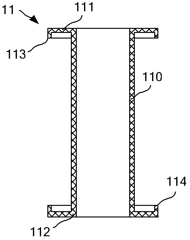
[0022] In this embodiment, the inner space of an elastic sheath 11 constitutes the axial pressure chamber 12 . Elastic sheath 11 structure such as figure 2 As shown, the sleeve body 110 is a ring structure, and the upper and lower ends of the sleeve body 110 extend radially outwards to form an upper mounting surface 111 and a lower mounting surface 112 respectively, and the upper mounting surface 111 and the lower mounting surface 112 are perpendicular to the sleeve body 110. The outer surface is flat to facilitate fixed installation. The elastic sheath 11 is made of fluorine rubber material, which has the function of high pressure and high temperature resistance. The elastic sheath 11 separates the axial pressure and the radial pressure of the rock-soil test piece 8 in the test piece chamber 120, so that the axial pressure and the radial pressure of the rock-soil test piece 8 are set independently, which can be The axial pressure is greater than or equal to the radial pressure, and the axial pressure can also be smaller than the radial pressure. While applying radial pressure, the axial pressure can be reduced or even zero, which can simulate the tension of rock and soil, and study the changes of various parameters of rock and soil that change with time when they are under tension, until they are destroyed. The outer sides of the upper mounting surface 111 and the lower mounting surface 112 have opposite axial outer ring edges, which are respectively the upper outer ring 113 and the lower outer ring 114. The upper outer ring 113 and the lower outer ring 114 can assist the upper mounting surface 111 and the lower outer ring. The installation on the installation surface 112 can also improve the strength of the sleeve body 110 . The rock-soil test piece 8 is installed in the elastic sheath 11 , and the space occupied by the rock-soil test piece 8 in the axial pressure chamber 1 is the test piece chamber 120 . The lower end of the upper cushion block 123 extends into the top of the elastic sheath 11 sealingly, thereby forming a sealed space between the lower end surface of the upper cushion block 123 and the upper end surface of the rock soil test piece 8, which is the upper pressure chamber 121 , the hydraulic pipeline of the upper pressure chamber 121 passes through the upper pad 123 . The upper end of the lower cushion block 124 extends into the bottom of the elastic sheath 11 sealingly, thereby forming a sealed space between the upper end surface of the lower cushion block 124 and the lower end surface of the rock soil test piece 8, which is the lower pressure chamber 122, The hydraulic pipeline of the lower pressure chamber 122 passes through the lower block 124 .
[0023] The annular pressure chamber 13 is formed in the space jointly defined by the upper end cover 131 , the lower end cover 132 , the cylinder body 130 and the elastic sheath 11 . The cylinder body 130 is a cylindrical structure with two ends open. The upper end cap 131 and the lower end cap 132 respectively seal the two ends of the cylinder body 130 and are screwed to the sealing cylinder body 130 . A gland 133 and an upper stopper 134 are also provided on the top of the annular pressure chamber 13 . The bottom of the annular pressure chamber 13 is also provided with a lower stopper 135 . The cylinder body 130 , the upper block 134 , the elastic sheath 11 and the lower end cover 132 are all in sealing contact to form a sealed annular pressure chamber 13 . The gland 133 is installed between the upper end cover 131 and the upper mounting surface 141 of the elastic sheath 14 .
[0024] A heating jacket 15 is also installed in the annular pressure chamber 13 . The heating jacket 15 is a closed ring structure and is installed between the upper stopper 134 and the lower stopper 135 . The heating jacket 15 is located in the pressure oil in the annular pressure chamber 13, and can directly heat the oil in the annular pressure chamber 13. Due to the convection of the oil, the heating speed is fast and the temperature of the oil rises evenly, which can reduce energy consumption and improve Accuracy of temperature control. The heating jacket 15 is connected with the external power supply through a sealed heating joint, which is resistant to oil corrosion and insulated from the oil. By adopting the heating jacket 15, the maximum temperature in the specimen chamber 10 can reach 100°C-150°C.
[0025] In addition, a rubber pad 16 is installed at the lower part of the pressure chamber 1, and the rubber pad 16 is fixedly mounted on the lower end surface of the lower block 132 to relieve the impact of the axial force. In addition to applying pressure and heat to the rock test piece 8, the pressure chamber 1 can also apply pore water, gas, etc. as required, to simulate more underground rock and soil environments.
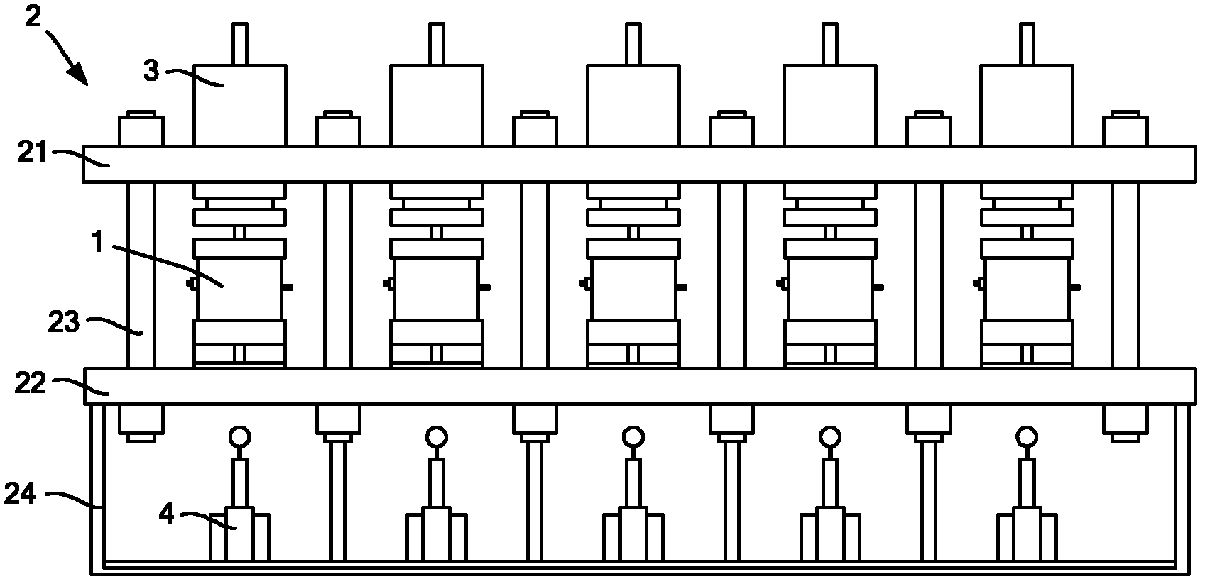
[0026] In this example, if image 3As shown, a total of 5 pressure chambers are installed on a test bench 2. The 5 pressure chambers can be set with the same test conditions and purposes, or different test conditions and purposes can be set according to the test needs. The five pressure chambers 1 can conduct rheological tests on five different rock and soil test pieces 8 at the same time, greatly shortening the rheological test period and increasing the test speed. The test bench 2 is used to support the pressure chamber 1 and includes an upper beam 21 , a lower beam 22 , a column 23 and a base 24 . Each of the upper beam 21 and the lower beam 22 is one piece, and five pressure chambers 1 are installed in parallel between the upper beam 21 and the lower beam 22 . Columns 23 are used to connect the upper beam 21 and the lower beam 22, one column 23 is installed at each of the four corners around each pressure chamber 1, a total of 12 columns 23, saving 8 columns compared with 5 separate rheometers , greatly reducing the production cost. The base 24 is installed on the lower part of the lower beam 22 for supporting the upper beam 21 , the pressure chamber 1 , the lower beam 22 and the column 23 . In addition, the axial environment system 3 is installed on the upper beam 21, and the radial environment system 4 is installed in the base 24, both of which are connected to the pressure chamber 1 through hydraulic pipelines, electric circuits, water pipes and air pipes. The axial environment system 3 and the radial environment system 4 respectively change the axial and radial stress field and temperature field of the rock-soil test piece 8 to simulate the actual underground environment of the rock-soil.
[0027] like Figure 4 and Figure 5 As shown, the geotechnical rheological test equipment of this embodiment includes a pressure chamber 1 , a test bench 2 , an axial environment system 3 , a radial environment system 4 , an energy supply system 5 , a detection system 6 and a control and analysis system 7 . The pressure chamber 1 and the test bench 2 have been introduced as before, and will not be repeated here. The axial environment system 3 adjusts the axial environment parameters such as the axial pressure in the pressure chamber 1 , and the radial environment system 4 adjusts the radial environment parameters such as the radial pressure in the pressure chamber 1 .
[0028] The energy supply system 5 provides the energy required by the equipment, including four parts: an oil supply module 51 , a power supply module 52 , an air supply module 53 and a water supply module 54 . The oil supply module 51 adopts a low-noise oil pump, a stainless steel oil tank and a high-precision oil filter, which can ensure the cleanliness of the oil circuit. Since the five pressure chambers 1 share one oil tank, the production cost of the oil tank can be greatly reduced, and the space occupied by the oil tank can be reduced. The power supply module 52 in the energy supply system 5 adopts a large-capacity uninterruptible power supply, and the gas-liquid booster pump and accumulator are used in the gas supply module 53 and oil supply module 51, which can avoid the impact of accidental power failure on the test . Among them, the power of the uninterruptible power supply can reach 2KW, the maximum working pressure of the gas-liquid booster pump can reach 0.69MPa, and the maximum output oil pressure can reach 30MPa.
[0029] like Figure 5 As shown, the detection system 6 includes a displacement sensor 61, a force sensor 62, a radial pressure sensor 63, a temperature sensor 64 and a circumferential extensometer. Among them, the hoop extensometer is only used in the uniaxial test without pressure chamber, and the above-mentioned displacement sensor 61, force sensor 62, radial pressure sensor 63, temperature sensor 64 and hoop extensometer test the geotechnical test in pressure chamber 1. Parameters of the hardware 8, and send the parameters to the control and analysis system 7. Wherein, the displacement sensor 61 can test the axial strain of the rock and soil specimen 8; the force sensor 62 can test the axial stress of the rock and soil specimen 8; the radial pressure sensor 63 can test the radial stress of the rock and soil specimen 8; The sensor 64 can test the temperature change of the rock-soil test piece 8 ; the annular extensometer can test the radial strain of the rock-soil test piece 8 .
[0030] The control and analysis system 7 is the brain of the device. On the one hand, the control and analysis system 7 collects the data sent by the detection system 6 for analysis and evaluation; on the other hand, the control and analysis system 7 generates control instructions and sends the instructions to the In the energy supply system 5, the axial environment system 3 and the radial environment system 4, the actions of the energy supply system 5, the axial environment system 3 and the radial environment system 4 are controlled to deliver suitable pressure oil to the pressure chamber 1, Electricity, gas and water etc. The control and analysis system 7 adopts visual operation and sets up an independent operation platform. The test data is stored and called in the form of Microsoft Office Excel, and any two parameters of stress, axial strain, radial strain, lateral pressure, temperature and effective time can be used as coordinates to draw graphs, curve analysis of test results, and local amplification. Test reports can also be compiled and printed. The control software of the control and analysis system 7 adopts the LabVIEW software of American NI Company, and is further developed and formed on the basis of this software. The use of LabVIEW software programming not only has the development potential, but also facilitates multi-control of one machine, and greatly reduces the cost.
[0031] The beneficial effect of the present invention is that, compared with the prior art, the present invention adopts the elastic sheath 11 to isolate the annular pressure chamber 13 in the pressure chamber 1 from the axial pressure chamber 12, so that the rock in the pressure chamber 1 The axial pressure and radial pressure of the soil test piece 8 are absolutely isolated, so that the axial pressure and radial pressure borne by the rock-soil test piece 8 in the test piece chamber 120 are independent of each other, and can be realized by applying pressure separately. The radial pressure and axial pressure of the rock-soil test piece 8 are compared with different values to simulate the stress field under various conditions such as rock-soil tension, so that the application occasions of the rock-soil rheological test are more extensive, and the test results are consistent. The reference value is greater, and the application level of geotechnical rheological tests can be greatly improved.
[0032] The technical solution of the present invention has been disclosed by the preferred embodiments as above. Those skilled in the art should realize that changes and modifications made without departing from the scope and spirit of the present invention disclosed by the appended claims of the present invention are within the protection scope of the claims of the present invention.