Multi-channel fluorescent light filter cubic box and fluorescence microscopy imaging system

A cubic box and optical filter technology, applied in the direction of fluorescence/phosphorescence, optical filter, microscope, etc., can solve the problems of high price, difficult to exceed 10 types, large volume of fluorescent imaging device, etc., and achieve the effect of compact structure

Inactive Publication Date: 2012-08-01
孔令华
View PDF9 Cites 12 Cited by
  • Summary
  • Abstract
  • Description
  • Claims
  • Application Information

AI Technical Summary

Problems solved by technology

For example, Chinese patent CN201110065302.3 "Excited Fluorescent Molecular Imaging System and Primary Fluorescence Imaging Method" uses two filter wheels respectively: an excitation filter wheel and an emission filter wheel. The volume of the filter wheel increases with the size of the filter. The increase of the number is almost quadratic, so the filter wheel suitable for multi-channel fluorescence observation (the number of channels is more than 3) is bulky because when the radius of the wheel is small, the surface of the wheel cannot cover the non-overlapping filters. Expand, if one or two of the filter wheels is replaced with a band-pass center frequency that can be adjusted to LCTF or AOF, the resulting fluorescence imaging device will be larger in size, more expensive, and lower in transmittance
[0011] To observe a fluorescent calibration object, there must be a corresponding fluorescence filter cube box. In order to facilitate the observation of different fluorophores, Chinese patent CN00217112. 0 "A Spectral Band Rapid Conversion Device for Fluorescence Microscope" discloses a method in which a plurality of excitation filters are placed on the excitation filter frame, and the excitation filter frame is inserted into the fluorescence filter frame from the hole in the shape of a drawer as a whole. Optical filter cube box, so that users can choose different excitation filters to insert into the box of fluorescence filter cube box when using, the disadvantage of this method is that when the number of excitation filters is large, the formed fluorescence filter The volume of the optical cube is large, and the user cannot choose different emission filters or dichroic mirrors or beam splitters. According to Table 1, there is a corresponding relationship between the excitation light and the emission light of different fluorophores, or each The excitation light / emission light band pairs of fluorophores are different. Often when the excitation light filter is changed, the emission light filter also needs to be changed. Due to the limited volume, this method can be used to achieve multi-channel fluorescence observation in fluorescence microscopy. Imaging systems usually only have 2-3 channels, and it is difficult to have more than 5 channels
[0012] In order to meet the requirements of excitation filter / emission filter / dichroic mirror required for the observation of various fluorophores, US Patent US6252664 discloses a plug-in fluorescent The filter cube, the bandpass filter used in this invention has several high-pass peaks in the wavelength range of 200 to 400 nm, the dichroic mirror allows (emission) light with a wavelength of 415-800 nm to pass, and The disadvantage of this method is that it requires a specially manufactured filter, and the number of fluorescent lights to be observed is difficult to exceed 10.

Method used


Image

  • Multi-channel fluorescent light filter cubic box and fluorescence microscopy imaging system
  • Multi-channel fluorescent light filter cubic box and fluorescence microscopy imaging system
  • Multi-channel fluorescent light filter cubic box and fluorescence microscopy imaging system

Examples


Embodiment Construction

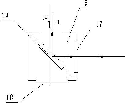
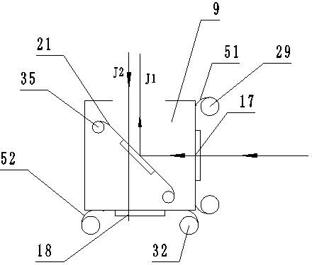
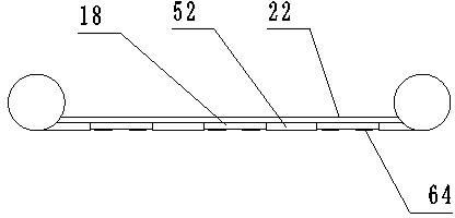
[0045] Such as image 3 , 5 , Shown in 6, a kind of multi-channel fluorescence filter cube box is to improve existing fluorescence filter cube box, the excitation filter, emission filter and dichroic mirror or The beamsplitter is rolled up like a film, so that a fluorescence filter cube can store multiple excitation filters, emission filters and dichroic mirrors or beamsplitters, and can observe a variety of fluorophores. It includes a box frame and an excitation filter group, an emission filter group, a dichroic mirror or a beam splitter group fixed on the box frame, and the excitation filter 17 and the emission filter 18 are respectively fixed on a cubic On the two vertical planes adjacent to the box 9, the dichroic mirror or beam splitter 19 is located on the angle plane of 45 degrees between the excitation filter 17 and the emission filter 18, between the cube box 9 and the emission filter There are holes 50 on the opposite surface of 18, and the excitation filter group ...


PUM


Abstract

The invention discloses a multi-channel fluorescent light filter cubic box. The multi-channel fluorescent light filter cubic box comprises an excitation light filter pack, a transmission light filter pack and a dichroscope or a spectroscope, wherein the excitation light filter pack and the transmission light filter pack are respectively fixed on two adjacent vertical planes on the cubic box, the dichroscope or the spectroscope is positioned at a 45-degree included angle surface between the excitation light filter pack and the transmission light filter pack, and the surface on the cubic box, opposite to the transmission light filter pack, is provided with holes. The invention has the key points that the excitation light filter pack is formed by embedding at least two excitation light filters on one bottom liner equidistantly, and two ends of the bottom liner are fixedly arranged on a turning wheel; and the transmission light filter pack is formed by embedding at least two transmission light filters on the other bottom liner equidistantly, and the two ends of the bottom liner are fixedly arranged on a turning wheel. According to the multi-channel fluorescent light filter cubic box disclosed by the invention, the storage of a large amount of filters can be easily realized in a smaller volume, and more than 10 types of fluorophores can be observed; and a fluorescence imaging device employing the multi-channel fluorescent light filter cubic box can perform high-resolution imaging on both the space and the spectrum.

Description

technical field [0001] The present invention relates to a fluorescent microscopic imaging device, in particular to a fluorescent filter cube device capable of modifying frequency bands of excitation light and emitted light in the fluorescent microscopic imaging device and a multi-channel fluorescent display device comprising the device. Micro imaging device. Background technique [0002] Fluorescence microscopy imaging system is the basic tool for current biomedical research, clinical medical research and pharmaceutical industry research. Excited fluorescence imaging technology is the most basic technology for observing the interaction process of genes, proteins, drugs and cells at the molecular level. In this imaging technology, the target substance of interest in biological samples and its distribution with space Observation, in a bioluminescent observation system or imaging system, generally requires imaging one or several characteristic bands of a certain target substan...

Claims


Application Information

Patent Timeline
Patent Type & Authority Applications(China)
IPC IPC(8): G01N21/64G01N21/59G02B27/00G02B7/00G02B5/20G02B21/36
Inventor 孔令华
Owner 孔令华
Why Eureka
Try Eureka