Projecting device

A projection device and mode measurement technology, applied in projection devices, optics, instruments, etc., can solve the problems of reduced lamp service life, abnormal operation of electronic parts, and shortened lamp life, so as to improve safety, reliability, and protection response. Fast and timely, the effect of improving lamp life

Inactive Publication Date: 2012-08-01
QISDA OPTRONICS (SUZHOU) CO LTD +1
View PDF0 Cites 6 Cited by
  • Summary
  • Abstract
  • Description
  • Claims
  • Application Information

AI Technical Summary

Problems solved by technology

[0004] However, most of the heat sources inside the projector come from the lamp, followed by the power board, main board, etc. When the air inlet and outlet of the projector are blocked and the internal temperature is too high, the service life of the lamp will be reduced, and the electronic parts will not work normally or even burn out.
The traditional technology only detects the objects entering the air vent, and only increases the rotation speed of the heat dissipation unit, but does not pay attention to the temperature inside the projection device. But at this time, the temperature of the electronic components may have reached more than 100 degrees, and there is a problem. Stabilization phenomenon, the temperature of the lamp is higher, resulting in a reduction in the life of the lamp

Method used


Image

  • Projecting device
  • Projecting device
  • Projecting device

Examples


Embodiment Construction

[0024] In order to have a further understanding of the purpose, structure, features, and functions of the present invention, the following detailed descriptions are provided in conjunction with the embodiments.

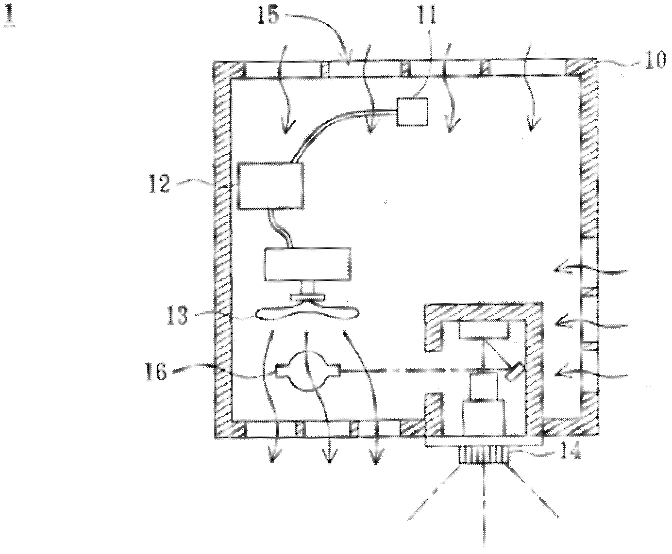
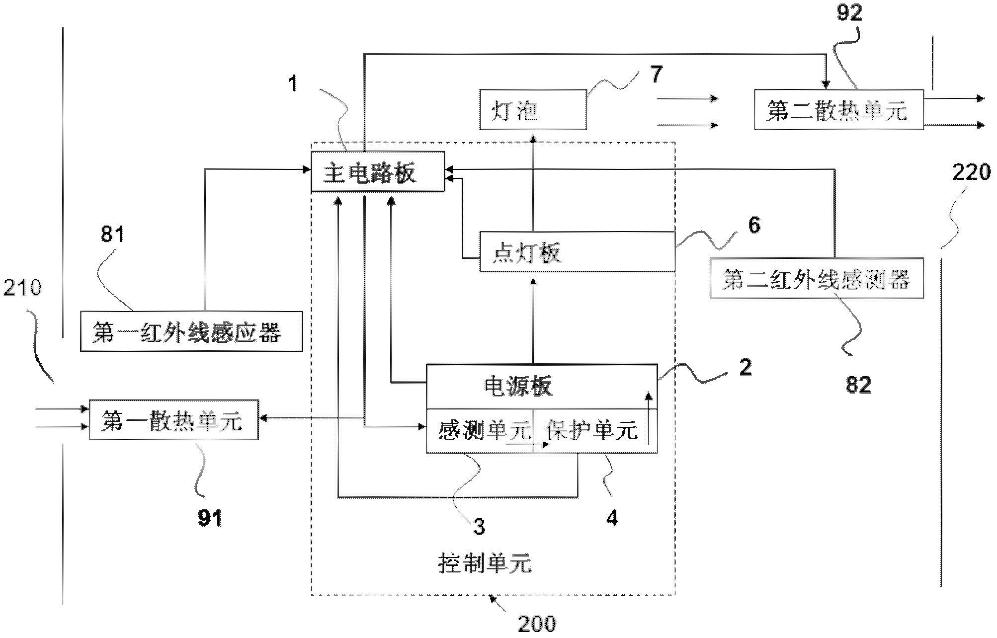
[0025] figure 2 It is a schematic structural diagram of a projection device according to an embodiment of the present invention. Such as figure 2 As shown, the projection device includes a control unit 200, a bulb 7, a first infrared sensor 81, a first fan 91, a second infrared sensor 82, and a second fan 92, wherein the first infrared sensor 81, The first fan 91, the second infrared sensor 82, and the second fan 92 are all electrically connected to the control unit 200, and the control unit 200 includes a main circuit board 1, a lighting board 6, and a power board 2, wherein the power board 2 It includes a sensing unit 3 and a protection unit 4 . The first fan 91 operates at a rotational speed A1, the second fan 92 operates at a rotational speed B1, and the bulb...


PUM


Abstract

The invention relates to a projecting device, which comprises a control unit, a heat dissipating unit, a sensing module group and an airflow through-hole, wherein the sensing module group is used for detecting objects at the airflow through-hole; the control unit comprises a fixed resistor; the fixed resistor has a first temperature threshold, a second temperature threshold and a third temperature threshold; the third temperature threshold is larger than the second temperature threshold which is larger than the first temperature threshold; when detecting that an object exists at the airflow through-hole, the sensing module group sends a signal to the control unit, so as to enable the temperature of the fixed resistor to rise; when the temperature of the fixed resistor reaches the first temperature threshold, a first overheat preventing mechanism is stated; when the temperature of the fixed resistor reaches the second temperature threshold, a second overheat preventing mechanism is stated; when the temperature of the fixed resistor reaches the third temperature threshold, a third overheat preventing mechanism is stated. The projecting device disclosed by the invention has the advantages that when the internal temperature of the projecting device is over high, three stages of protective devices are triggered, so that the efficiency of an electronic circuit is steady and the life of a lamp bulb is prolonged.

Description

technical field [0001] The present invention relates to a projection device, and in particular to a device with a sensing module to detect whether the air inlet or outlet of the device is blocked by foreign objects to reduce the heat dissipation effect and activate the anti-overheating mechanism projection device. Background technique [0002] Whether it is for business or leisure purposes, the use of projectors is mainly to enlarge and project images on the screen. The main components of a traditional projector are a projection lens, an optical engine, and a light bulb. After the light emitted by the bulb passes through the optical engine, the image is projected onto the screen by the projection lens. When using a projector, the lamp must be continuously lit, and its luminous intensity must be sufficient to project a magnified image on the screen. As the bulb continues to glow, its heat will continue to increase. At the same time, when the light is emitted to the optica...

Claims


Application Information

Patent Timeline
Patent Type & Authority Applications(China)
IPC IPC(8): G03B21/16G03B21/14H05K7/20
Inventor 江俊明
Owner QISDA OPTRONICS (SUZHOU) CO LTD
Why Eureka
Try Eureka