Insulator device
A technology for insulators and mounting bases, applied to insulators, lead-in/through-type insulators, electrical components, etc., can solve the problems of complex processing and long production time, and achieve the effect of avoiding complicated processes, simple processing, and ensuring sealing performance
- Summary
- Abstract
- Description
- Claims
- Application Information
AI Technical Summary
Problems solved by technology
Method used
Image
Examples
Embodiment 1
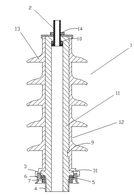
[0030] A kind of insulator device 1, the specific structure sees figure 1 , figure 1 It is the usual setting method in the state of use, so follow the figure 1The sections shown in define the upper and lower parts of this insulator assembly. The insulator device 1 of the present invention includes a resin inner core 11, the resin inner core 11 has a central axis hole 15, a rubber layer 12 is wrapped on the outside of the resin inner core 11, and the outer wall of the rubber layer 12 A plurality of rubber umbrella skirts 13 are arranged on it. A metal terminal 2 is arranged on the top of the resin inner core 11 , and a connecting assembly is arranged on the lower part of the resin inner core 11 . The specific arrangement of the connection assembly is as follows: a blocking surface 3 is formed on the lower part of the resin inner core 11, in this embodiment, between the upper end and the lower end of the resin inner core 11 and close to the lower end A boss 31 is arranged on...
Embodiment 2
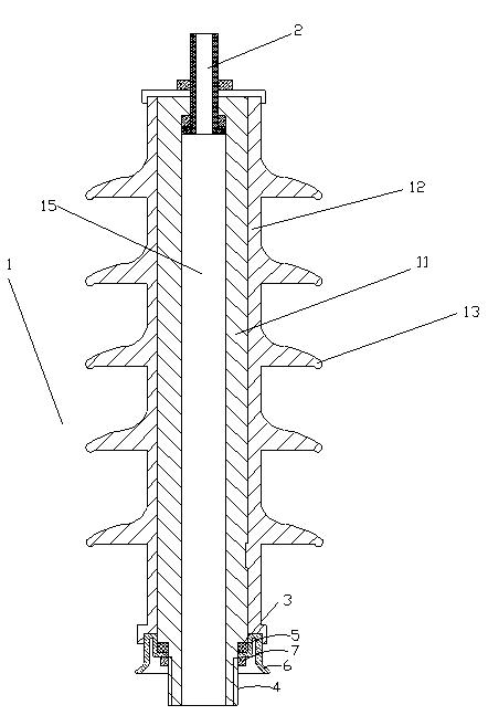
[0032] Another embodiment of the present invention is an insulator device 1, the specific structure is shown in figure 2 , including a resin inner core 11, the resin inner core 11 has a central axis hole 15, a rubber layer 12 is wrapped on the outside of the resin inner core 11, and a plurality of rubber umbrellas are arranged on the outer wall of the rubber layer 12 skirt13. A metal terminal 2 is arranged on the upper end of the resin inner core 11 , and a connecting assembly is arranged on the lower part of the resin inner core 11 . The specific arrangement of the connection assembly is as follows: the resin inner core 11 has a large diameter and a small diameter from top to bottom, and the blocking surface 3 is when the resin inner core 11 changes from a large diameter to a small diameter. The end surface formed at a diameter of , the thread 4 extends from the lower end of the resin core 11 to the blocking surface 3 . At the lower part of the blocking surface 3, a sealin...
Embodiment 3
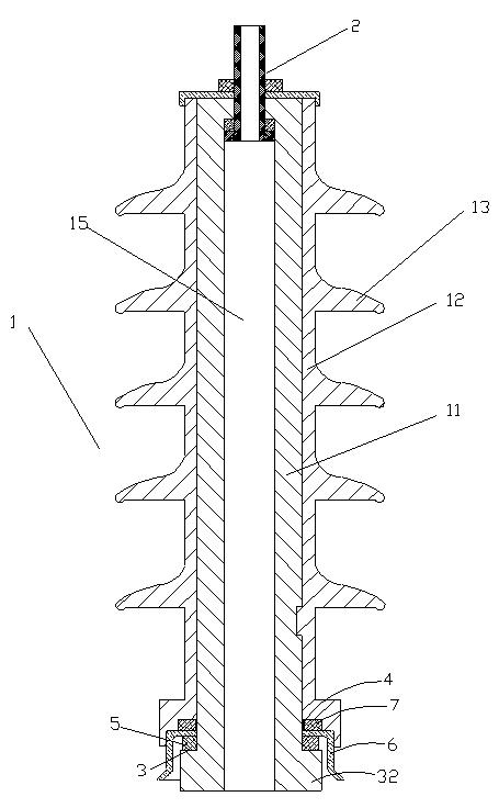
[0034] Another embodiment of the present invention is an insulator device 1, the specific structure is shown in image 3 , including a resin inner core 11, the resin inner core 11 has a central axis hole 15, a rubber layer 12 is wrapped on the outside of the resin inner core 11, and a plurality of rubber umbrellas are arranged on the outer wall of the rubber layer 12 skirt13. A metal terminal 2 is provided at the upper end of the resin core 11 , and a connection assembly is provided at the lower end of the resin core 11 . The specific arrangement of the connection assembly is as follows: the lower end of the resin core 11 forms a bottom boss 32, the blocking surface 3 is the upper end surface of the bottom boss 32, and the thread 4 protrudes from the bottom. The top of the platform 32 extends to the upper end of the resin core 11, and the thread 4 here can only be provided with a section, and at the position close to the bottom boss 32, it can be screwed into the fastening nu...
PUM
 Abstract
Description
Claims
Application Information
 - R&D
- Intellectual Property
- Life Sciences
- Materials
- Tech Scout
- Unparalleled Data Quality
- Higher Quality Content
- 60% Fewer Hallucinations
Browse by: Latest US Patents, China's latest patents, Technical Efficacy Thesaurus, Application Domain, Technology Topic, Popular Technical Reports.
© 2025 PatSnap. All rights reserved.Legal|Privacy policy|Modern Slavery Act Transparency Statement|Sitemap|About US| Contact US: help@patsnap.com


