

High-voltage motor bearing axial force
A high-voltage motor, axial force technology, applied in electrical components, electromechanical devices, electric components, etc., can solve the problem of unsatisfactory axial force bearing effect, and achieve significant cooling effect, ensure normal operation, and reasonable structure.
Inactive Publication Date: 2012-08-01
NANTONG WELL ELECTRIC MOTOR
View PDF2 Cites 0 Cited by
- Summary
- Abstract
- Description
- Claims
- Application Information
AI Technical Summary
Problems solved by technology
[0002] Due to structural reasons, the existing high-voltage motors are not ideal for bearing axial force
Method used
View moreImage
Smart ImageViewing Examples

Examples
Embodiment Construction
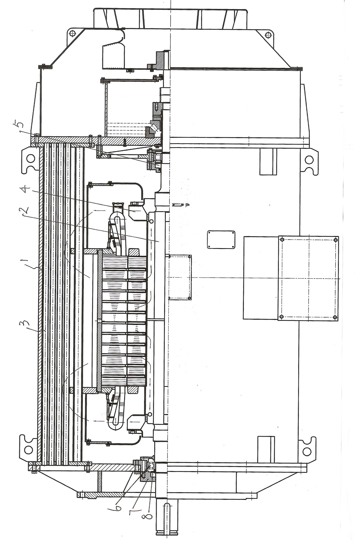
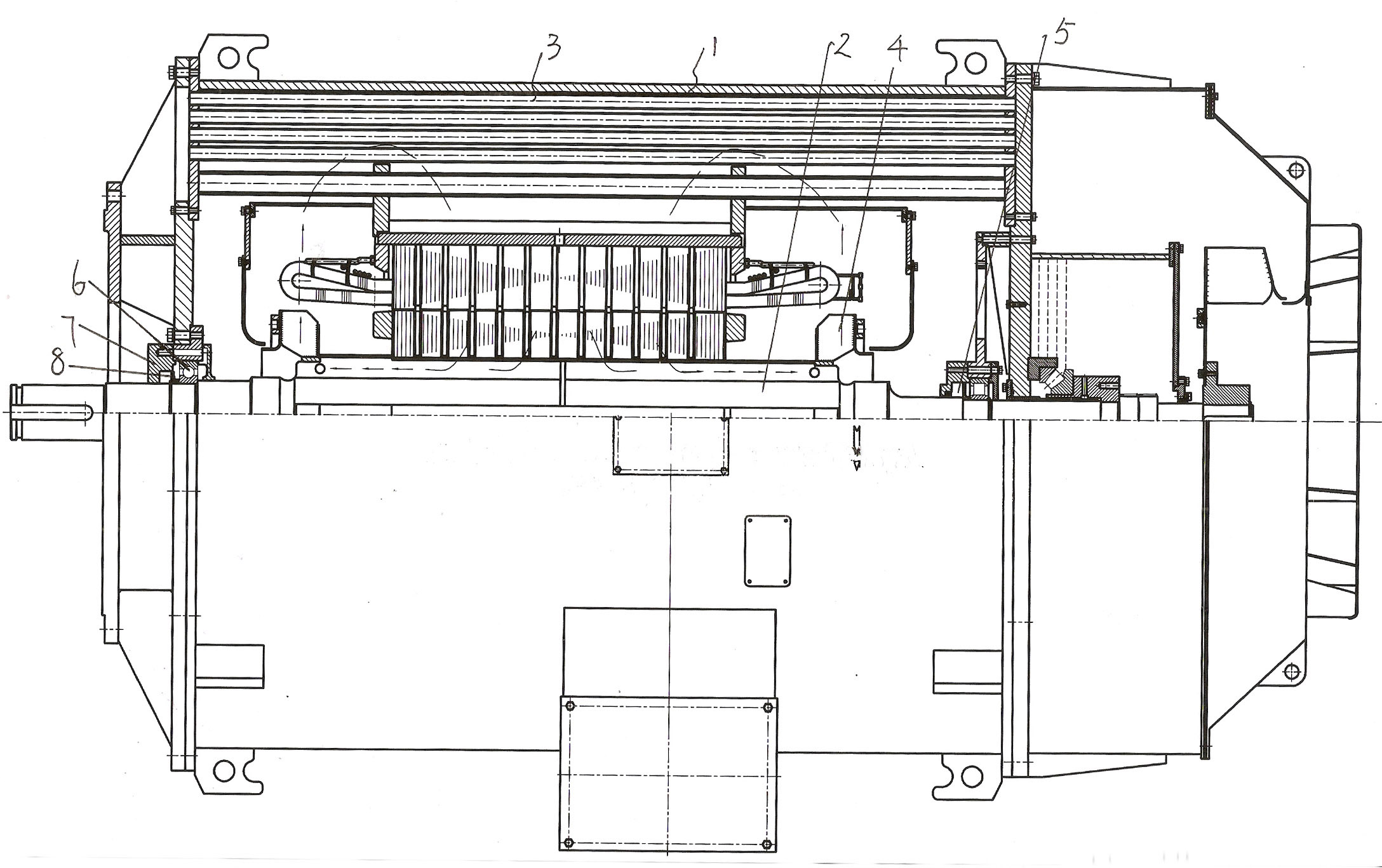
[0009] A high-voltage motor bearing axial force, comprising a casing 1, a motor rotor 2, a cooling pipe 3 is arranged on the air duct in the casing, a cooling centrifugal fan 4 is arranged on the motor rotor; front and rear bearings are respectively arranged at the front and rear parts of the motor shaft, and the motor A set of cylindrical roller bearings 5 is arranged in the middle of the shaft; the front and rear bearings include a bearing main body 6, and a bearing outer cover 7 is arranged outside the bearing main body, and an oil deflector ring is arranged between the bearing main body and the bearing outer cover to prevent grease from overflowing in the bearing main body 8.
Login to View More PUM
 Abstract
The invention discloses a high-voltage motor bearing axial force. The high-voltage motor comprises an enclosure and a motor rotor. The high-voltage motor is characterized in that: cooling tubes are arranged on an air duct in the enclosure; a cooling centrifugal fan is arranged on the motor rotor; a front bearing is arranged on the front part of a motor shaft, and a rear bearing is arranged on the rear part of the motor shaft; a set of cylindrical roller bearing is arranged on the middle part of the motor shaft; each of the front and rear bearings comprises a bearing main body; an outer bearing cover is arranged outside each bearing main body; and an oil deflector ring for preventing oil overflowing out of the bearing main body is arranged between the bearing main body and the outer bearing cover. The high-voltage motor has the characteristics of rational and simple structure, high air speed, high air volume and remarkable cooling effects.
Description
technical field [0001] The invention relates to a high-voltage motor. Background technique [0002] Due to reasons such as structure, the existing high-voltage motors are not ideal for bearing axial force. Contents of the invention [0003] The purpose of the present invention is to provide a high-voltage motor with reasonable structure and good cooling effect to withstand axial force. [0004] Technical solution of the present invention is: [0005] A high-voltage motor bearing axial force, including a casing and a motor rotor, is characterized in that: a cooling pipe is arranged on an air duct in the casing, a cooling centrifugal fan is arranged on the motor rotor; front and rear bearings are respectively arranged at the front and rear parts of the motor shaft, and A set of cylindrical roller bearings is arranged in the middle of the shaft; the front and rear bearings include a bearing main body, a bearing outer cover is arranged outside the bearing main body, and an o...
Claims
Login to View More Application Information
Patent Timeline
 Patent Type & AuthorityApplications(China)
IPC IPC(8): H02K9/04H02K5/16
Inventor季立新成友贤
OwnerNANTONG WELL ELECTRIC MOTOR