Electromotor dynamic/stable stage parameter identification method based on stator resistance observer

A stator resistance and motor technology, applied in electronic commutation motor control, motor generator control, control generator and other directions, can solve the problems of voltage model error, reduced estimation accuracy, rotor speed and rotor resistance identification difficulties, etc.

Inactive Publication Date: 2012-08-01
CHONGQING JIAOTONG UNIVERSITY
View PDF3 Cites 37 Cited by
  • Summary
  • Abstract
  • Description
  • Claims
  • Application Information

AI Technical Summary

Problems solved by technology

However, there are two problems in the above method: if the operating frequency of the motor is the same as or very close to the frequency of the injected current (1-3Hz), it will not only fail to meet the "full excitation" condition, but will cause the pulsating component of the injected current. Bring more torque ripple
Therefore, in the case of "the operating frequency is the same or very close to the frequency of the injected current", this method cannot be used; even if this method can solve the problem of "the operating frequency is the same or very close to the frequency of the injected current", due to the need to increase The corresponding injection current equipment not only increases the fault source, but also complicates the structure of the industrial application itself, which is not easy to realize
[0005]Secondly, when using the MRAS method to identify the rotor speed and rotor resistance, there is a problem in the identification accuracy: when the motor is working at a low speed, the rotor speed and rotor resistance The identification of rotor resistance is a difficult point, and it is also a current research hotspot
When the motor is running at low speed, the accuracy of speed estimation is quite sensitive to the model parameter error inside the motor. In the MRAS method, the reference model usually uses the voltage model as the standard model, and the voltage model contains stator resistance. During operation, the motor temperature The change of frequency will cause the stator resistance in the voltage model to change accordingly, which will bring errors to the voltage model, especially at low speed and close to zero speed, the measurement error will even submerge the back electromotive force, which will cause the speed and the accuracy of rotor resistance estimation during transients is greatly reduced, deteriorating the operating performance of the motor at low speeds

Method used


Image

  • Electromotor dynamic/stable stage parameter identification method based on stator resistance observer
  • Electromotor dynamic/stable stage parameter identification method based on stator resistance observer
  • Electromotor dynamic/stable stage parameter identification method based on stator resistance observer

Examples


Embodiment

[0155] In order to verify the effect brought by the present invention, the motors using the existing method and the method of the present invention were compared experimentally at different given rotational speed values. The experiments were performed at a load of 12 N . m (approximately 85.7% of the rated value), the speed setting is low speed, that is, it is carried out under the condition that the speed setting changes suddenly between 80~30rpm / min. The parameters of the induction motor used in the experiment are as follows: rated power , rated voltage , rated current ,Rated speed , stator resistance , rotor resistance , stator inductance , rotor inductance , mutual inductance , rated torque ,Number of pole pairs ,Moment of inertia .

[0156] attached Figure 13 is the motor speed value obtained according to the existing identification method, the dotted line in the figure is the given speed value, and the solid line is the actual speed value. Whe...


PUM


Abstract

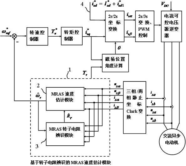
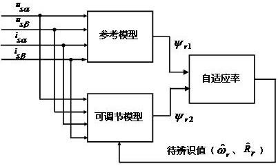
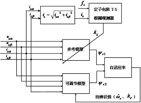
The invention discloses an electromotor dynamic / stable stage parameter identification method based on a stator resistance observer. For the parameter identification at a dynamic stage of an electromotor, a stator resistance T-S (Takagi-Sugeno) fuzzy observer is introduced to obtain an actually-measured value of stator resistance on the basis that the existing MRAS (Model Reference Adaptive System) method is still adopted, and dynamic correction is carried out on a rotating speed reference model and a resistance reference model according to the actually-measured value of the stator resistance; and for the parameter identification at a stable stage, the identification method for the rotating speed of a rotor is achieved by adopting the MRAS method and the stator resistance T-S fuzzy observer which are the same as those adopted in the parameter identification at the dynamic stage, and the identification method for the resistance of the rotor is achieved by adopting simple conversion. The electromotor dynamic / stable stage parameter identification method based on the stator resistance observer has the beneficial technical effects that the problem of inaccurate reference models is solved, the low-speed operating performance of the electromotor can be improved, the adoption of a current injection method is avoided, the current injection equipment is saved, the complexity of a system is lowered, the introduction of torque ripple is avoided, and the like.

Description

technical field [0001] The invention relates to an on-line identification technology of induction motor parameters without a speed sensor, in particular to an identification method of electric motor dynamic / steady state phase parameters based on a stator resistance observer. Background technique [0002] In sensorless vector control systems of induction motors, the model reference adaptive method (also called MRAS method) is widely used in sensorless AC speed control systems due to its simple principle, easy implementation and good stability. [0003] In the sensorless vector control system based on MRAS method, the identification of motor parameters can be divided into two parts: dynamic phase and steady state phase. Many methods for estimating motor parameters online explicitly or implicitly require the motor to be in a dynamic process. In actual operation, the motor flux is usually in a steady state for a long time, and it is difficult to obtain the motor parameters in t...

Claims


Application Information

Patent Timeline
Patent Type & Authority Applications(China)
IPC IPC(8): H02P21/14
Inventor 徐凯徐文轩许强徐果薇
Owner CHONGQING JIAOTONG UNIVERSITY
Why Eureka
Try Eureka