
Oscillation device

An oscillation device and oscillation circuit technology, applied in power oscillators, electrical components, output stability, etc., can solve the problems of fundamental wave M-order stray interference, difficult and high-precision temperature compensation, complex circuits, etc., and achieve good correlation. , the effect of high-precision temperature compensation

Active Publication Date: 2012-08-01
NIHON DEMPA KOGYO CO LTD
View PDF7 Cites 15 Cited by
  • Summary
  • Abstract
  • Description
  • Claims
  • Application Information

AI Technical Summary

Problems solved by technology

[0009] However, this method is as described in paragraph 0019. Regarding the desired output frequency f0 and the respective frequencies f1 and f2 of the two crystal oscillators, it is necessary to adjust the crystal oscillator so that it becomes Therefore, not only the manufacturing process of the crystal oscillator becomes complicated, but also there is a problem that a high yield cannot be obtained.
In addition, if Figure 4 As shown, since the clock as the frequency signal from each crystal oscillator is counted for a certain period of time, and the difference (f1-f2) is obtained, the detection time directly affects the detection accuracy, and it is difficult to perform high-precision temperature compensation
In addition, since the fundamental wave and overtone frequency are extracted from one crystal oscillator, the circuit becomes complicated, and the M-order spur of the fundamental wave and fm interfere.

Method used


Image

  • Oscillation device
  • Oscillation device
  • Oscillation device

Examples


Embodiment Construction

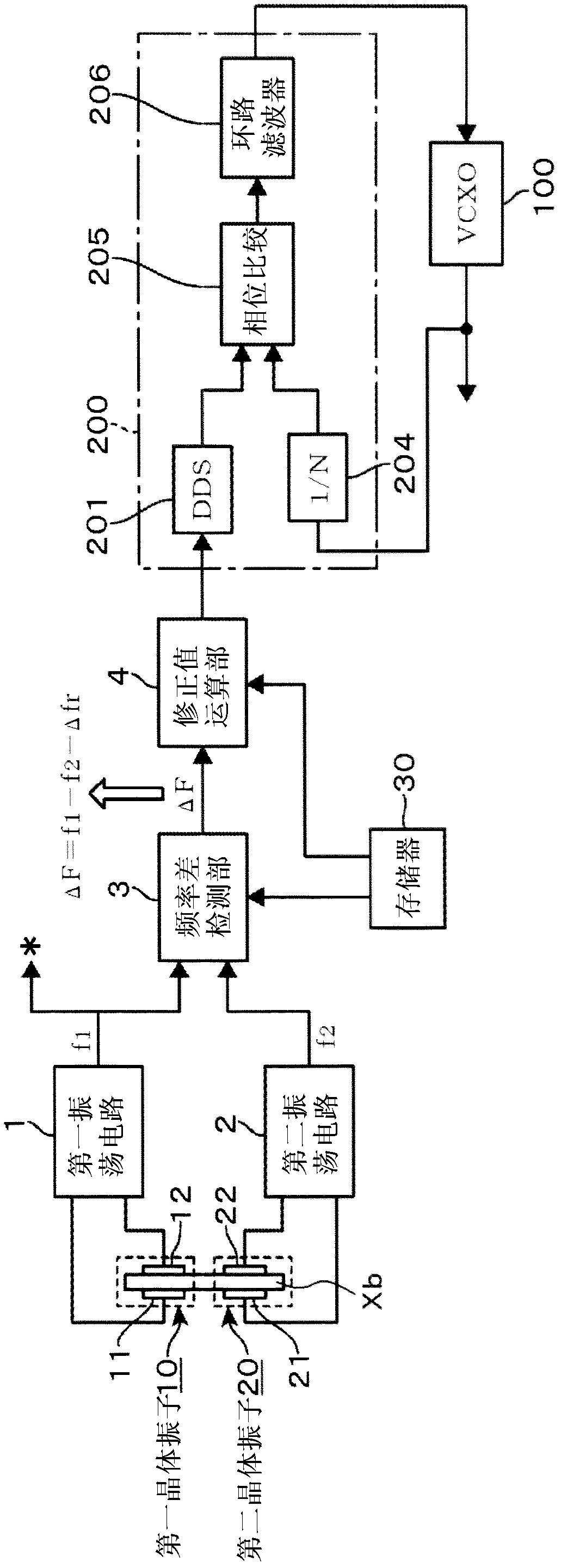
[0059] figure 1 It is a block diagram showing the whole embodiment of the oscillation device of the present invention. The oscillation device is a TCXO configured as a frequency synthesizer that outputs a frequency signal of a set frequency, and includes: a voltage-controlled oscillator 100 using a crystal resonator; a control circuit unit 200 that constitutes a PLL of the voltage-controlled oscillator 100; and a temperature compensation unit that performs temperature compensation of the reference clock input to the control circuit unit 200 . There is no symbol for the temperature compensation part, which is equivalent to figure 1 The part on the left side of the control circuit unit 200 .

[0060] The control circuit unit 200 forms a reference clock based on a sawtooth wave output from a DDS (Direct Digital Synthesizer: Direct Digital Synthesizer) circuit unit 201 . Furthermore, it is a structure in which the output signal obtained by frequency-dividing the output of the...


PUM


Abstract

An oscillation device capable of highly accurate temperature compensation of an output frequency is provided. The oscillation device includes: first and second oscillator circuits oscillating first and second quartz-crystal resonators with overtones respectively; a frequency difference detecting part finding a value corresponding to a difference value between values corresponding to differences between f1 and f1r and between f2 and f2r, where f1 and f2 are oscillation frequencies of the first and second oscillator circuits, and f1r and f2r are oscillation frequencies of the first and second oscillator circuits at a reference temperature; and a correction value obtaining part which, based on the value corresponding to the difference value and a relation between the value corresponding to the difference value and a frequency correction value of the oscillation frequency f1, obtains the frequency correction value of f1, wherein the output frequency is corrected based on the found frequency correction value.

Description

technical field [0001] The invention relates to an oscillating device which detects the temperature of a placed crystal oscillator and performs temperature compensation of an output frequency based on the temperature detection result. Background technique [0002] TCXO is called a temperature-compensated crystal oscillator. By combining the temperature characteristics of a crystal oscillator and the opposite circuit characteristics, it can obtain better temperature characteristics than a single crystal oscillator in a wide temperature range. In addition, TCXOs not only have excellent temperature characteristics, but also have features such as small size, light weight, and short start-up time, so they are used as reference oscillators for measurement equipment such as various communication equipment, frequency counters, and synthesizers. [0003] TCXO has a temperature compensation circuit including a temperature sensing element. As the temperature compensation circuit, there...

Claims


Application Information

Patent Timeline
Patent Type & Authority Applications(China)
IPC IPC(8): H03B5/04
CPCH03L1/026H03L7/18
Inventor 赤池和男佐藤信一
Owner NIHON DEMPA KOGYO CO LTD
Learn More