Output power control method of burst mode laser driver

A laser driver and output power technology, applied in transmission systems, electromagnetic wave transmission systems, electrical components, etc., can solve problems such as optimization of unfavorable duty cycles, errors, and inability to accurately reflect the average transmission power of optical transmitters, etc., to avoid Uncertainty, reducing device cost, avoiding long-term cumulative effects

Inactive Publication Date: 2012-08-01
SOUTHEAST UNIV
View PDF4 Cites 21 Cited by
  • Summary
  • Abstract
  • Description
  • Claims
  • Application Information

AI Technical Summary

Problems solved by technology

[0008] The problems with this method are: it is necessary to agree on the relevant communication protocols; it is necessary to formulate a unified international standard; if there is no unified international standard, or there is no agreement on the relevant mechanism in the existing international standard, it may affect the Compatibility between networking devices
[0010] The problem with this approach is that for a burst mode transmitter, the laser only emits light during the enable period, when there is an effective monitoring current to generate
[0012] The problem with this method is that the object of sampling and holding is to monitor the instantaneous value of the current
Randomly and simply sampling at a certain moment may sample the monitoring current value when there are more random data "0", which cannot accurately reflect the actual average transmission power of the optical transmitter
If this value is regarded as a constant output power reference value over a long period of time, large errors may result
[0013] In addition, this method can only monitor the comprehensive superposition effect of the bias current and the pulse modulation current, and cannot separately reflect the influence of the bias current and the pulse modulation current on the output power of the optical transmitter, which is not conducive to the optimization of the duty cycle

Method used


Image

  • Output power control method of burst mode laser driver
  • Output power control method of burst mode laser driver

Examples


Embodiment Construction

[0044] In order to solve the above technical problems and achieve the purpose of automatically controlling the output power of the laser driver and optimizing the extinction ratio of the output light pulse, the present invention proposes the following method:

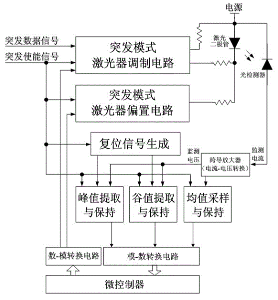
[0045] The monitoring current signal generated by the photodetector (photodiode) is converted into a corresponding monitoring voltage signal using a transconductance amplifier. In the burst mode optical transmitter system, add peak value extraction, valley value extraction and mean value extraction and corresponding holding circuits.

[0046] According to the control of the burst enable signal, when entering the burst enable period, the peak value, valley value and average value of the monitoring voltage obtained by the above three extraction circuits respectively; when entering the burst disable period, the three voltage values Storage remains.

[0047] When a new burst enable cycle starts, the reset signal generation...


PUM


Abstract

The invention provides an automatic output power control method of a burst mode laser driver and a specific implementation mode for realizing the method. The method comprises the following steps of: additionally arranging a peak value extraction circuit, a valley value extraction circuit and a mean value extraction circuit in a burst mode laser driver system; converting a burst-mode light power monitoring current signal into a voltage signal by utilizing a transconductance amplifier, respectively extracting the peak value, valley value and mean value of the voltage signal, maintaining, and periodically resetting and updating; converting the peak value, the valley value and the mean value of the voltage signal into corresponding numerical values by utilizing a low-cost analog-to-digital conversion circuit; subtracting the numerical value of the valley value from the numerical value of the peak value by utilizing a microcontroller and comparing an obtained difference value with a preset reference value; comparing the numerical value of the light power mean value with a preset reference value; and according to comparative results, respectively regulating the control voltages of the modulation circuit and bias circuit of the laser driver by utilizing a digital-to analog conversion circuit, so as to realize automatic power control and achieve the optimized extinction ratio.

Description

technical field [0001] The invention relates to a method for automatically controlling the output power of a burst mode laser driver of an optical network unit device in a passive optical network system, and a specific implementation manner for realizing the method. Background technique [0002] Fiber-to-the-home is the development trend of the access network. Ethernet passive optical network combines the advantages of Ethernet and passive optical network, and is currently a popular technology for realizing fiber-to-the-home [1] . [0003] The basic structure of the Ethernet passive optical network system is embodied as a point-to-multipoint network [1-2] . Among them, in the downlink direction, the data packets sent by the optical cable terminal equipment pass through one or more stages of passive optical splitters, and are simultaneously transmitted to multiple optical network units in a broadcast manner. In the upstream direction, the data packets sent by each optical...

Claims


Application Information

Patent Timeline
Patent Type & Authority Applications(China)
IPC IPC(8): H04B10/155H04B10/564
Inventor 林叶朱恩顾皋蔚张望伟叶宁
Owner SOUTHEAST UNIV
Why Eureka
Try Eureka