Distributed DALI (Digital Addressable Lighting Interface) lighting control system and method thereof

A lighting and control system technology, applied in lighting devices, light sources, electric light sources, etc., can solve the problems of lost users of remote control equipment, overwhelmed network, violation of design ideas, etc., to avoid address duplication configuration, improve network transmission environment, The effect of improving transmission efficiency

Inactive Publication Date: 2012-08-01
ZHEJIANG UNIV
View PDF5 Cites 19 Cited by
  • Summary
  • Abstract
  • Description
  • Claims
  • Application Information

AI Technical Summary

Problems solved by technology

First of all, the above three solutions use the network topology structure of DALI protocol with single master and multiple slaves, and use the idle resources of the single-chip microcomputer of the slave control device to realize localization and expansion control. Although this can solve the localization control problem of the small bay of the DALI lighting system, But at the same time, it also introduces the overlap between the functions of the controller and the actuator, which violates the design idea of ​​separating the controller and the actuator of the DALI protocol.
Secondly, the additional data protocol reduces the compatibility and openness of the DALI lighting system and cannot be compatible with other DALI devices. The data l

Method used


Image

  • Distributed DALI (Digital Addressable Lighting Interface) lighting control system and method thereof
  • Distributed DALI (Digital Addressable Lighting Interface) lighting control system and method thereof
  • Distributed DALI (Digital Addressable Lighting Interface) lighting control system and method thereof

Examples


Embodiment Construction

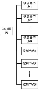
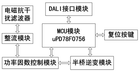
[0055] like Figure 1-3 As shown, the distributed DALI lighting control system includes a DALI gateway, multiple ballast nodes, and multiple control nodes; wherein, the sum of the number of ballast nodes and control nodes is less than or equal to 63; the DALI gateway and each ballast The node is connected to each control node; the ballast node includes an electromagnetic interference filter module, a rectifier module, a power factor control module, a half-bridge inverter module, a DALI interface module, an MCU module, and a reset button; the MCU module is connected to the DALI interface module, The half-bridge inverter module, the power factor control module, and the reset button are connected. The power factor control module is connected to the rectifier module, the half-bridge inverter module, and the electromagnetic interference filter module. The MCU module uses the DALI dimming special chip uPD78F0756; Power supply module, DALI interface module, MCU module, display module...


PUM


Abstract

The invention discloses a distributed DALI (Digital Addressable Lighting Interface) lighting control system and a method thereof. The system comprises a DALI gateway, a plurality of ballast nodes and a plurality of control nodes, wherein the DALI gateway and the control nodes serve as main control equipment, the ballast nodes serve as subordinative control equipment, the DALI gateway can control all the control nodes and all the ballast nodes, and the main control nodes can control the ballast nodes bond with a radio frequency identification (RFID). After the system is established, the DALI gateway automatically allocate addresses for the control nodes or the ballast nodes accessing a network newly, thereby reducing work load of engineering staff. Network communication among system equipment is performed through an anti-collision token transmission strategy based on master-slave equipment, thereby meeting communication requirements on a network with multiple masters and multiple slaves, and enhancing utilization efficiency of the network. By virtue of the RFID which is bond with the ballast nodes in a room, light in the room can be intuitively controlled by a user, so that the usability of the system is improved.

Description

technical field [0001] The invention relates to a lighting control system, in particular to a distributed DALI lighting control system and a method thereof. Background technique [0002] With the development of society and economy, people's demand for energy is increasing. With the intensification of oil and electric energy energy crisis, the development of new energy and energy conservation and emission reduction have become the common demands of all countries in the world. "Green Lighting Project" is a lighting concept proposed by the US National Environmental Protection Agency in the early 1990s from the perspective of energy conservation and environmental protection, and has been valued by the United Nations and countries around the world. Governments of various countries actively adopt corresponding policies and technical measures to promote the implementation and development of green lighting projects. [0003] In traditional buildings, the lighting system consumes 50...

Claims


Application Information

Patent Timeline
IPC IPC(8): H05B41/36
Inventor 曹晓萍仲玉芳黄忠吴明光
Owner ZHEJIANG UNIV
Why Eureka
Try Eureka