Center feeding die-casting mold

A center-feeding, die-casting mold technology, applied in the field of die-casting molds, can solve problems such as scrapping and deformation of die-casting parts, and achieve the effects of easy exhaust, convenient demoulding and material return, and simple and practical structure

Active Publication Date: 2012-08-08
宁波环亚机械制造有限公司
View PDF10 Cites 1 Cited by
  • Summary
  • Abstract
  • Description
  • Claims
  • Application Information

AI Technical Summary

Problems solved by technology

[0003] The purpose of the present invention is to overcome the problem that the feeding port of the die-casting mold of the ring-shaped and complicated peripheral shape is located on one side of the die hole, and there will be differences in the strength of the die-casting parts in all directions, and the die-casting parts are prone to deformation or even Insufficient scrapping, providing a center-feed die-casting die that has close strength in all directions of the die-casting, and the die-casting is not easy to be deformed and scrapped

Method used


Image

  • Center feeding die-casting mold
  • Center feeding die-casting mold
  • Center feeding die-casting mold

Examples


Embodiment Construction

[0018] The present invention will be further described below in conjunction with the accompanying drawings.

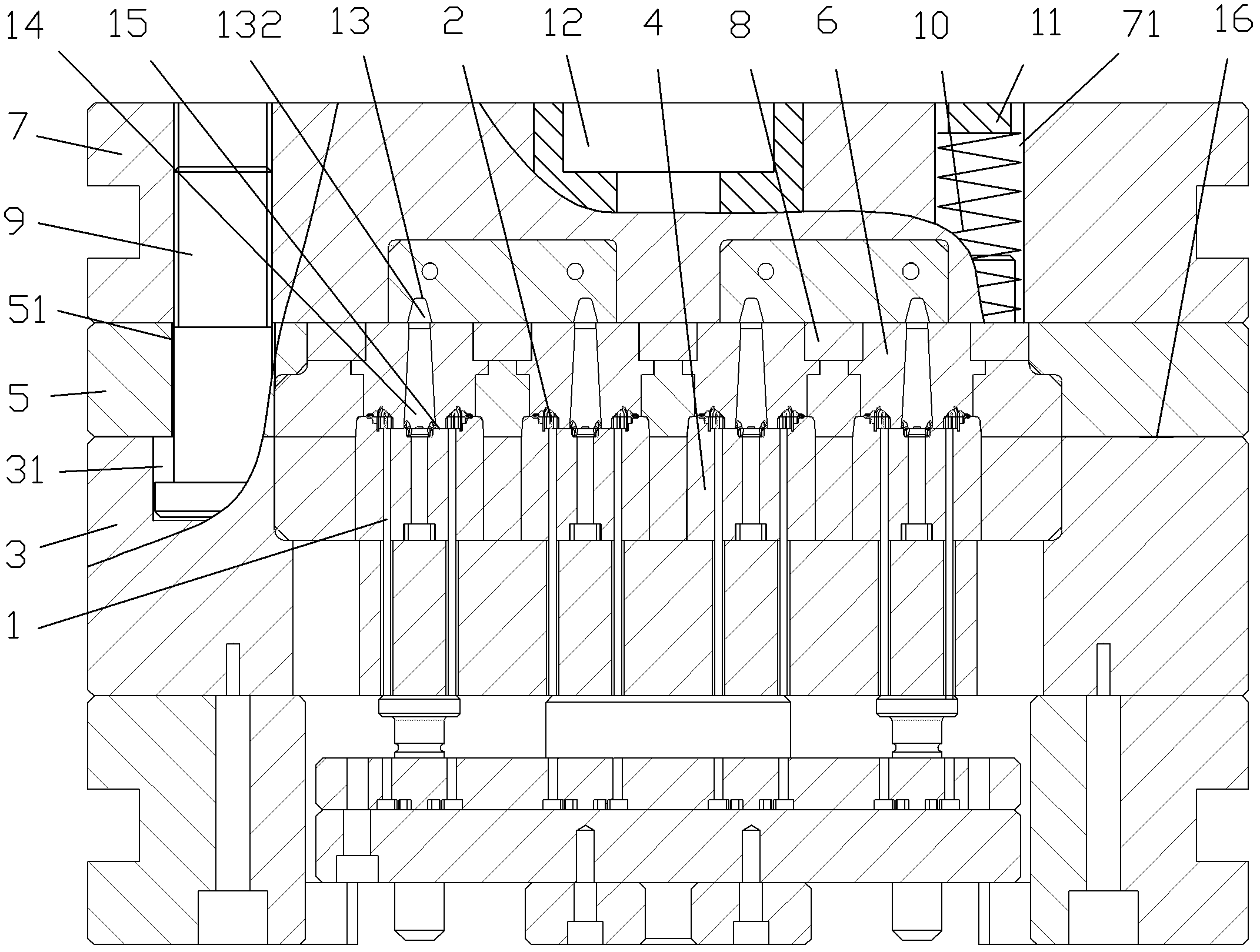
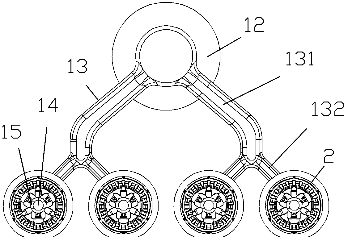
[0019] as attached figure 1 , attached figure 2 Shown: a center-feed die-casting mold, including a fixed mold, a movable mold, a runner system and eight ejector pins 1 located at the movable mold; the fixed mold and the movable mold are enclosed to form four cavities 2; The cavity 2 described is an annular cavity 2.

[0020] The movable mold includes a movable mold base 3 and four movable mold cores 4 whose number is equal to that of the cavity 2 and connected with the movable mold base 3 by screws.

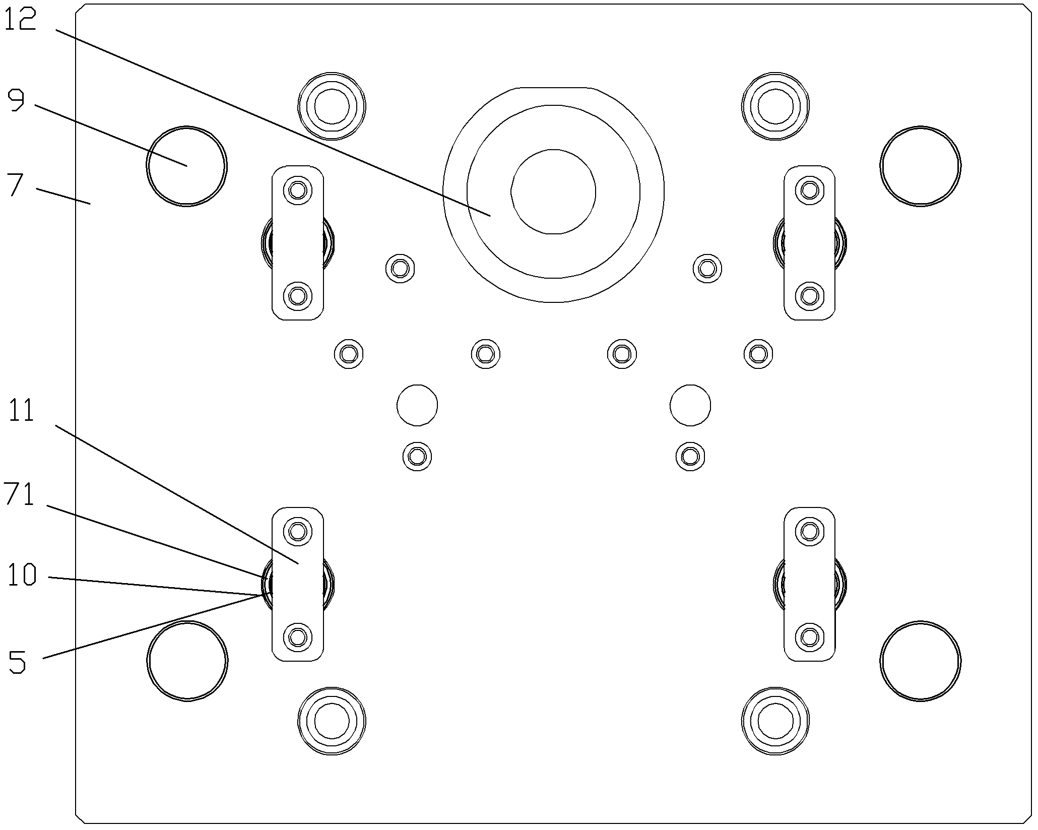
[0021] The fixed mold includes a fixed template 5, four fixed mold kernels 6 equal in number to the 4 movable mold kernels, a cover plate 7, a fixed plate 8, four limit guide nails 9, four clip springs 10 and Four pressing plates 11 whose number is equal to the number of stage clips 10; the fixed mold core 6 is located in the fixed template 5 and corresponds to the mo...


PUM


Abstract

The invention relates to the field of die-casting molds and aims at providing a center feeding die-casting mold enabling a die-casting piece to be close in strength in all directions and not apt to deform or discard. The center feeding die-casting mold comprises a fixed mold, a moving mold, a runner system and a plurality of ejector rods located at the position of the moving mold. The fixed mold and the moving mold are enclosed to form a plurality of annular mold cavities. The runner system comprises a material barrel, cross runners and feeding runners with the same number as the mold cavities. At least two feeding ports evenly distributed in the circumferential directions are arranged outside the feeding runners which are coaxial with the mold cavities, the feeding ports are communicated with the inner circumferences of the mold cavities, and the material barrel is communicated with the feeding runners through the cross runners. The center feeding die-casting mold enables the die-casting piece to be close in strength in all directions and not apt to deform or discard.

Description

technical field [0001] The invention relates to the field of die-casting moulds, in particular to a center-feed die-casting die which has close strength in all directions of the die-casting parts and is not prone to deformation and scrapping of the die-casting parts. Background technique [0002] For some annular die-casting parts with complex outer peripheral shapes, such as LED lighting radiators with several heat sinks distributed on the outer periphery and several pre-cast through holes distributed along the circumference on the end face, if these aluminum alloy die-casting parts adopt general When the runner system is used for die-casting, the strength of the die-casting parts in all directions will be different, and the die-casting parts will be easily deformed or even scrapped; the invention of the Chinese patent announcement number CN201776428U discloses a rotor die-casting mold runner plate, including a plate, and the plate has a Four mold holes, the mold holes are ...

Claims


Application Information

Patent Timeline
Patent Type & Authority Applications(China)
IPC IPC(8): B22D17/22
Inventor 庄美杰
Owner 宁波环亚机械制造有限公司
Why Eureka
Try Eureka