
Hydraulic driving-based wind turbine and control method thereof

A technology of hydraulic transmission and control method, which is applied to the control of wind turbines, the combination of wind turbines and wind motors, etc., which can solve the problems of high load and impact force of wind turbines, complex power electronic devices, and energy transmission loss, etc., so as to avoid Rigid impact, realizing variable speed and constant frequency control, cost saving effect

Inactive Publication Date: 2012-08-08
ZHEJIANG UNIV
View PDF6 Cites 20 Cited by
  • Summary
  • Abstract
  • Description
  • Claims
  • Application Information

AI Technical Summary

Problems solved by technology

The speed of the low-speed permanent magnet synchronous generator and the grid frequency are rigidly coupled, and the constantly fluctuating wind speed will input variable energy to the low-speed permanent magnet synchronous generator, which not only brings high load and impact to the wind turbine, but also Can't run in optimized mode
Using a frequency converter between the low-speed permanent magnet synchronous generator and the grid can solve the coupling problem between the rotational speed and the grid frequency, but the power electronic devices are usually complicated and expensive. Intermediary equipment is used, which will also cause energy transmission loss

Method used


Image

  • Hydraulic driving-based wind turbine and control method thereof
  • Hydraulic driving-based wind turbine and control method thereof
  • Hydraulic driving-based wind turbine and control method thereof

Examples


Embodiment Construction

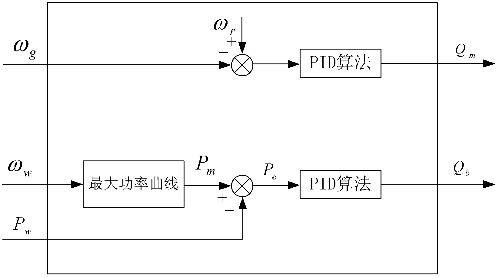
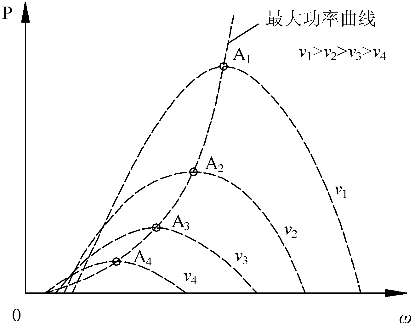
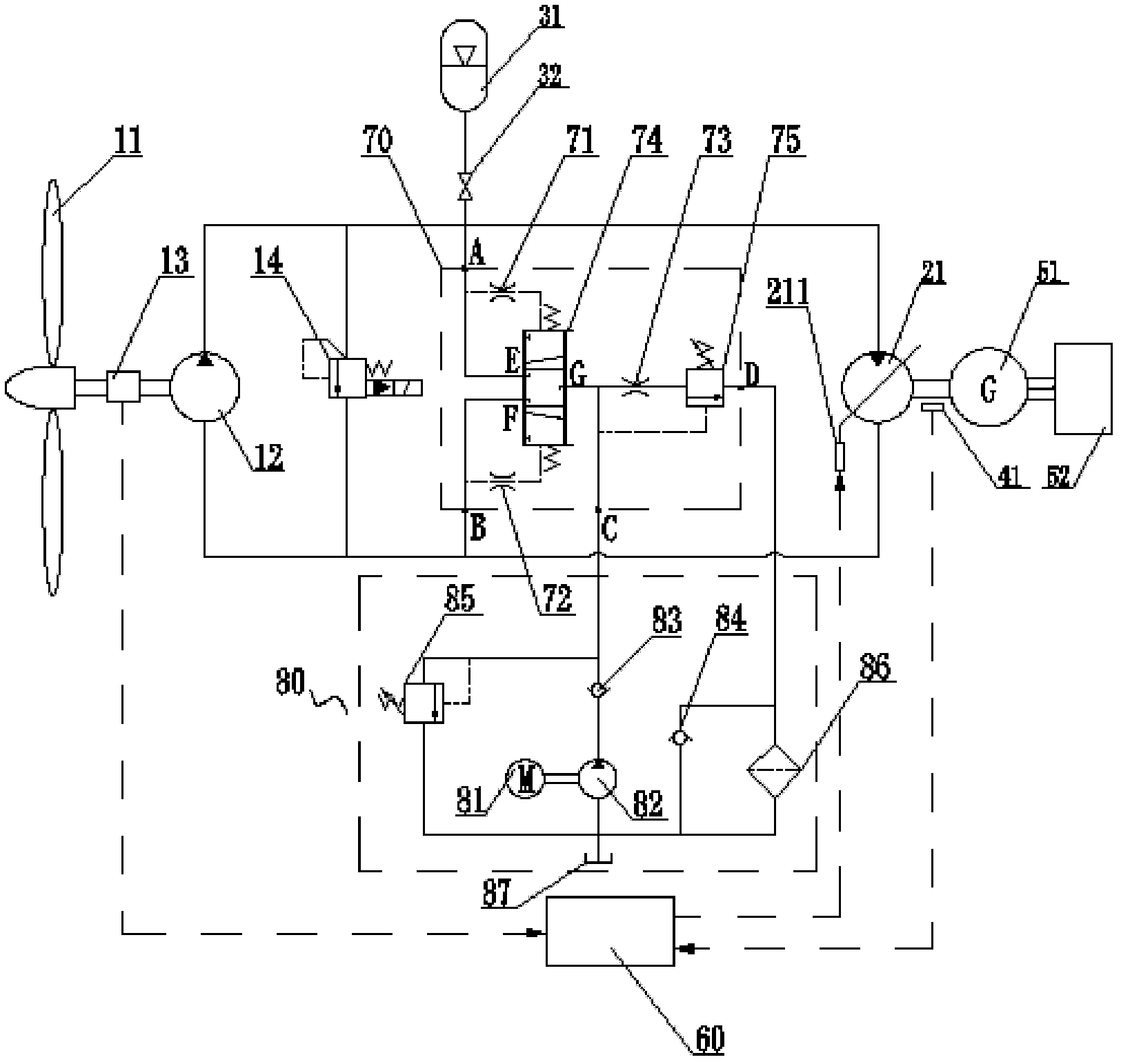
[0029] Refer to attached figure 1 And attached figure 2 . The invention discloses a wind turbine control method, the specific content is as follows:

[0030] 1) The wind turbine captures wind energy through the impeller, and the impeller converts the wind energy into mechanical energy and transfers the energy to the quantitative hydraulic pump, which converts the input mechanical energy into hydraulic energy output, and the hydraulic energy output by the quantitative hydraulic pump passes through the pipe The circuit is transmitted to the variable hydraulic motor, and the hydraulic energy output by the quantitative hydraulic pump is buffered through the accumulator. The variable hydraulic motor converts the input hydraulic energy into mechanical energy for output, the variable hydraulic motor drives the permanent magnet synchronous generator to rotate and output electric energy, and the output end of the permanent magnet synchronous generator is directly connected to the po...


PUM


Abstract

The invention relates to a hydraulic driving-based wind turbine and control method thereof. The control method of the wind turbine comprises the following steps of: realizing the transmission from an impeller to a generator by adopting a hydraulic driving mode; before synchronization, controlling the adjustment of the displacement of a variable hydraulic motor by a controller through detecting the rotating speed of a permanent magnet synchronous generator to realize the constant frequency control of the permanent magnet synchronous generator and enabling the output frequency of the permanent magnet synchronous generator to meet the synchronization requirement; and after synchronization, controlling the adjustment of the displacement of the variable hydraulic motor by the controller through detecting the rotating speed and the output power of the impeller to realize the variable speed control of the impeller and enabling the impeller to capture maximum wind energy. According to the hydraulic driving-based wind turbine disclosed by the invention, the stepless speed change can be realized by adopting the hydraulic driving mode; an energy accumulator can absorb energy fluctuation caused by transient wind speed, so that rigid impact on the wind turbine due to the fluctuation of wind speed can be avoided to a certain degree. On the basis of realizing the constant frequency control, the utilization rate of energy can be increased and the cost is saved.

Description

technical field [0001] The invention belongs to the field of wind power generation, and in particular relates to a wind power machine based on hydraulic transmission and a control method thereof. Background technique [0002] A wind turbine is a device that captures wind energy and converts it into electricity. Since wind energy is an energy source with great instantaneous changes, when the wind turbine is connected to the grid, the frequency of the electricity generated by the wind turbine is required to be consistent with the frequency of the grid. In order to solve the contradiction between the instantaneous change of wind energy and the constant grid frequency, a method widely used at present is variable speed and constant frequency control of wind turbines. Variable speed and constant frequency means that during the operation of the wind turbine, the speed of the generator is controlled to capture the maximum wind energy as the wind speed changes, and the constant freq...

Claims


Application Information

Patent Timeline
IPC IPC(8): F03D9/00F03D7/00F03D11/02F15B1/02F16H39/42
CPCY02E10/723Y02E10/722Y02E10/72Y02P70/50Y02P80/10
Inventor 林勇刚齐家龙刘宏伟李伟
Owner ZHEJIANG UNIV
Learn More