Gas permeability test device

A technology of gas permeability and testing equipment, which is applied in the direction of measuring equipment, permeability/surface area analysis, suspension and porous material analysis, etc. It can solve the problem that the sample cannot be effectively sealed and controlled, the testing process cannot be fully controlled, and multi-chamber The test cannot be independently controlled and other problems, so as to avoid the interference of external adverse factors, improve the detection accuracy, and achieve the effect of comprehensive control

Inactive Publication Date: 2012-08-08
LABTHINK INSTR
View PDF4 Cites 20 Cited by
  • Summary
  • Abstract
  • Description
  • Claims
  • Application Information

AI Technical Summary

Problems solved by technology

[0006] The present invention is to solve the problems existing in the prior art that can only meet the detection requirements of the barrier performance of general materials, the testing process cannot be fully controlled, the multi-cavity test cannot be independently controlled, the sample cannot be effectively sealed and the test chamber ca

Method used


Image

  • Gas permeability test device
  • Gas permeability test device
  • Gas permeability test device

Examples


Example Embodiment

[0026] Example 1:

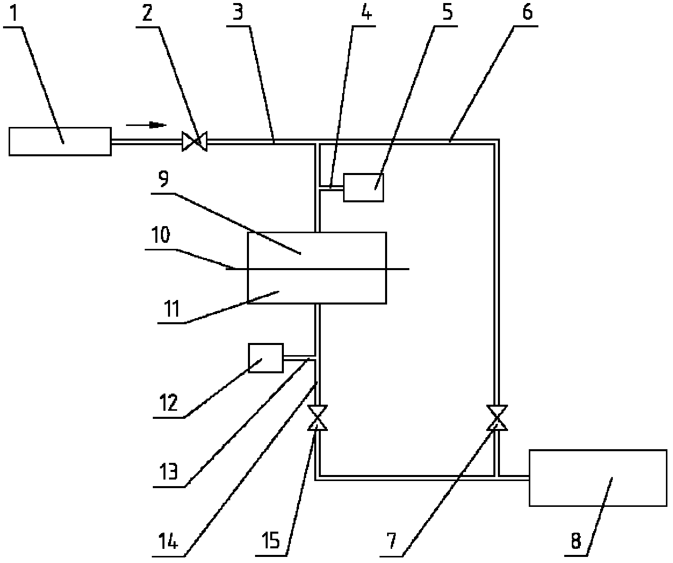
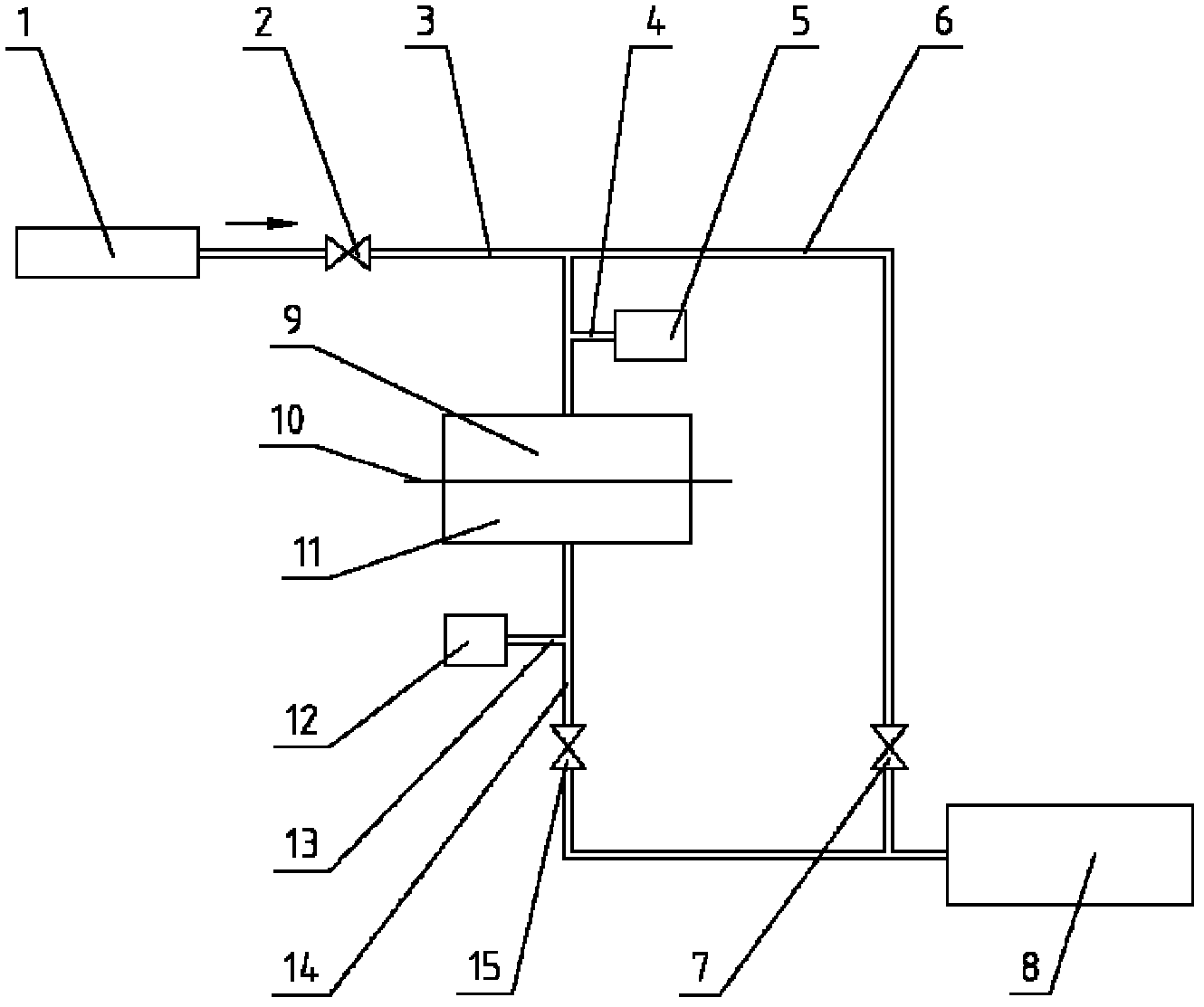
[0027] A gas permeability testing device, combined figure 1 , Including six parts of permeation pool, connecting pipeline, vacuum pump 8, pressure sensor, valve, and gas source. The permeation cell is divided into a test chamber 11 and a test gas chamber 9 by the sample 10; the test chamber 11 is connected to the pressure sensor I12, and is connected to the vacuum pump 8 through the pipeline I14, and the pipeline I14 is provided with a valve I15; the test gas chamber 9 It is connected to the pressure sensor II5, and is respectively connected to the vacuum pump 8 and the test gas source 1 through the pipeline II6 and the pipeline III3. The pipeline II6 is provided with a valve II7, and the pipeline III3 is provided with a valve III2. The vacuum pump 8 is connected to the test chamber 11 and the test gas chamber 9 through the pipeline I14 and the pipeline II6, respectively. By controlling the state of the valve I15 and the valve II7, it can vacuumize each side o...

Example Embodiment

[0029] Example 2:

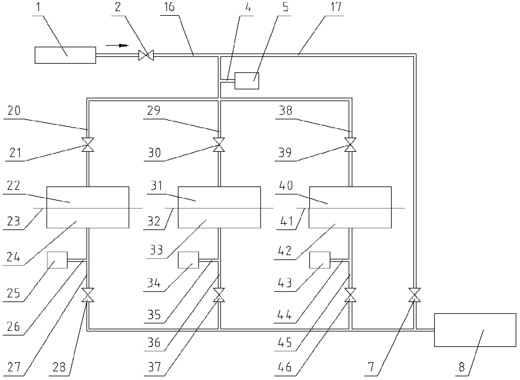
[0030] A gas permeability testing device, combined figure 2 , Is a three-cavity test structure of the present invention, that is, the number of permeation cells can be increased in the present invention to increase the test station and realize independent control for multi-cavity testing. It includes six parts: permeation pool, connecting pipeline, vacuum pump 8, pressure sensor, valve, and gas source. Each permeation cell is divided into two parts: test chamber and test gas chamber by sample. 1# permeation cell is divided into 1# test chamber 24 and 1# test gas chamber 22 by 1# sample 23, and 2# permeation cell is divided into two parts. #Sample 32 is divided into 2# test chamber 33 and 2# test gas chamber 31. 3# permeation cell is divided into 3# test chamber 42 and 3# test gas chamber 40 by 3# sample 41. Each test cavity is connected to the corresponding pressure sensor I, and is respectively connected to the vacuum pump 8 through the pipeline I. The pip...


PUM


Abstract

The invention discloses a gas permeability test device. The gas permeability test device comprises a vacuum pump and a permeation pool, wherein the permeation pool is divided into a test chamber and a test gas chamber; the vacuum pump is connected with the test chamber and the test gas chamber respectively through pipelines; a valve I and a valve II are respectively arranged on the pipelines through which the vacuum pump is connected with the test chamber and the test gas chamber; the test chamber is connected with a pressure sensor I; the test gas chamber is connected with a pressure sensor II; the test gas chamber is connected with the gas source of the test gas through a pipeline III; and a valve III is arranged on the pipeline III. The gas permeability test device has the advantages that the structure is simple; the gas permeability test device is reliable in use and convenient in application; the test chamber is vacuumized independently; the test sample and the test chamber are effectively sealed through the pressure difference between the test gas chamber and the test chamber; the test chamber is vacuumized completely; and the test process can be controlled completely and multi-chamber test can be controlled independently.

Description

technical field [0001] The invention relates to the technical field of barrier property detection, in particular to a gas permeability test device for detecting materials. Background technique [0002] With the continuous improvement of the level of science and technology, the production and development of packaging materials are gradually developing in the direction of lighter, thinner, more convenient and more economical. , The impact of the quality and safety of industrial products has made the importance of gas transmission rate testing increasingly prominent. At the same time, with the increasing understanding of product characteristics and the popularization and application of new packaging methods, only the oxygen transmission rate of materials is not enough to meet actual needs, so the transmission rates of other gases, such as nitrogen transmission rate and carbon dioxide transmission rate , helium gas transmission rate and other indicators are gradually increasing...

Claims


Application Information

Patent Timeline
IPC IPC(8): G01N7/00G01N15/08
Inventor 姜允中
Owner LABTHINK INSTR
Why Eureka
Try Eureka