

Method for circulating current restraining of parallel system of dual grid-connected inverters based on zero voltage vector feedforward control
A circulating current suppression and feedforward control technology, applied in the direction of converting AC power input to DC power output, electrical components, and single-network parallel feeding arrangement, etc., can solve problems such as slow dynamic response, and achieve high dynamic response speed and control effect. Effect
- Summary
- Abstract
- Description
- Claims
- Application Information
AI Technical Summary
Problems solved by technology
Method used
Image

Examples
specific Embodiment approach 1
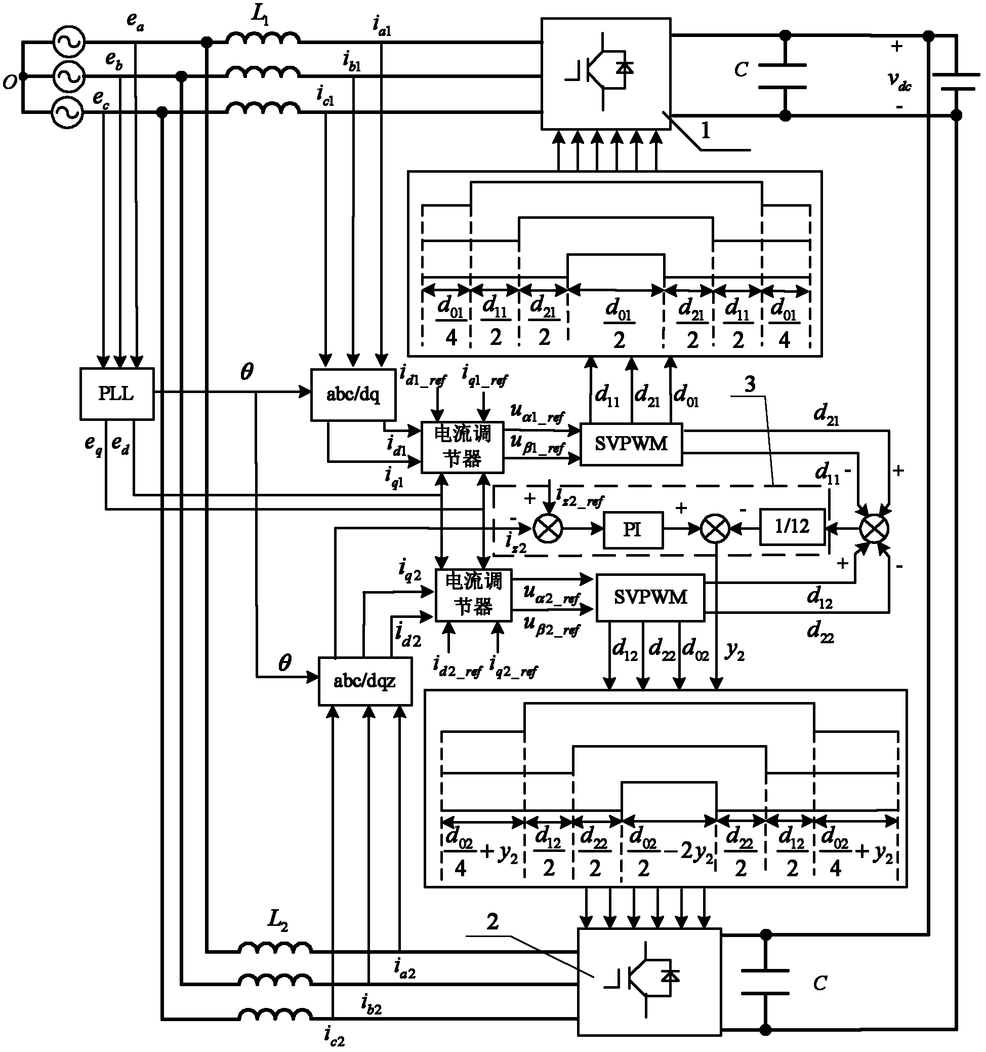
[0034] Specific implementation mode one: the following combination Figure 1 to Figure 10 This embodiment will be described. The method for suppressing circulation in a parallel system of dual grid-connected inverters based on voltage zero-vector feedforward control described in this embodiment, the dual grid-connected inverters share an AC bus and a common DC bus, and the circulating current suppression The method is based on the PI control method of the inverter parallel system,
[0035] The circulating current suppression method is to control the circulating current of an inverter in the double grid-connected inverter, and it includes the following steps:
[0036] Step 1: To the zero-sequence current i of the second inverter 2 z2 to sample;
[0037] Step 2: Using the zero sequence current controller 3 to control the zero sequence current i of the second inverter 2 z2 and the given zero-sequence current i of the second inverter 2 z2_ref Perform PI adjustment, and divide ...
specific Embodiment approach 2
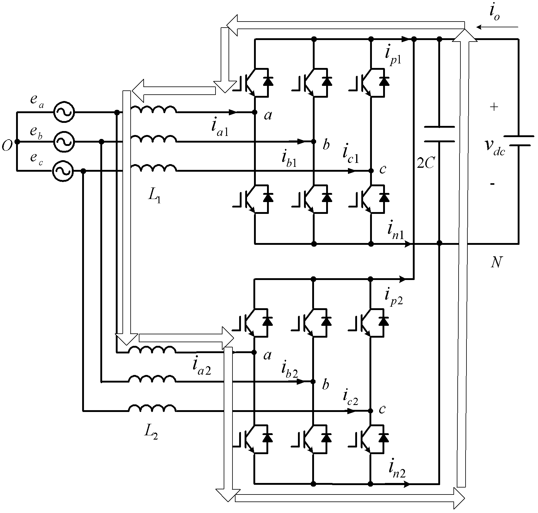
[0040] Specific implementation mode two: the following combination figure 1 Describe this embodiment, this embodiment is a further description of Embodiment 1, the zero-sequence current i of the second inverter 2 z2 for:
[0041] i z2 = i a2 + i b2 + i c2 ,
[0042] where i a2 is the a-phase current of the second inverter 2, i b2 is the b-phase current of the second inverter 2, i c2 is the c-phase current of the second inverter 2 .
specific Embodiment approach 3
[0043] Specific implementation mode three: the following combination Figure 1 to Figure 10 Describe this embodiment, this embodiment is a further description of Embodiment 2, the correction value y of the second inverter zero vector output by the zero-sequence current controller 3 2 for:
[0044] y 2 = ( K p _ z + K i _ z s ) · ( i z 2 _ ref - i z 2 ) - Δ d ...
PUM
 Abstract
Description
Claims
Application Information