
Axial electrical excitation composite rotor circumferential misplacement reluctance motor control system and method

A compound rotor and reluctance motor technology, applied in the control system, AC motor control, electrical components, etc., can solve the problems of small phase torque output, motor pulsation, etc., and achieve the goal of reducing excitation current, improving reliability and improving performance Effect

Pending Publication Date: 2017-10-24
SHENYANG POLYTECHNIC UNIV
View PDF6 Cites 7 Cited by
  • Summary
  • Abstract
  • Description
  • Claims
  • Application Information

AI Technical Summary

Problems solved by technology

There are two main reasons for the torque ripple: one is that the special double-salient pole structure of the motor determines that there must be a large torque ripple, especially at the position where the stator and rotor are aligned, where the reluctance is the smallest and the flux linkage is saturated. The phase torque output is the smallest; the second is that the motor is used in the operating environment that requires frequent switching of the power converter, that is, the complex voltage harmonic components other than the fundamental wave will be generated during frequent switching, which will also cause the pulsation of the motor

Method used


Image

  • Axial electrical excitation composite rotor circumferential misplacement reluctance motor control system and method
  • Axial electrical excitation composite rotor circumferential misplacement reluctance motor control system and method
  • Axial electrical excitation composite rotor circumferential misplacement reluctance motor control system and method

Examples


Embodiment Construction

[0050] An embodiment of the present invention will be described in detail below in conjunction with the accompanying drawings.

[0051] In this embodiment, a control system with DSP28335 as the core is set up, and the motion process of the motor is controlled by a double closed-loop PI control strategy of current and speed. Through the motor control system based on DSP as the core, the electromagnetic torque is used to the maximum extent to increase the output torque of the motor and increase the speed regulation range. The control system detects and collects the position feedback and winding current feedback of the motor, and transmits it to the controller DSP for comparison processing. The comparison result is calculated by the DSP to calculate the motor speed to control the opening and closing of the power switch tube IGBT. The precise control of current feedback requires A speed regulator and a current regulator are introduced into the control system to form a current nega...


PUM


Abstract

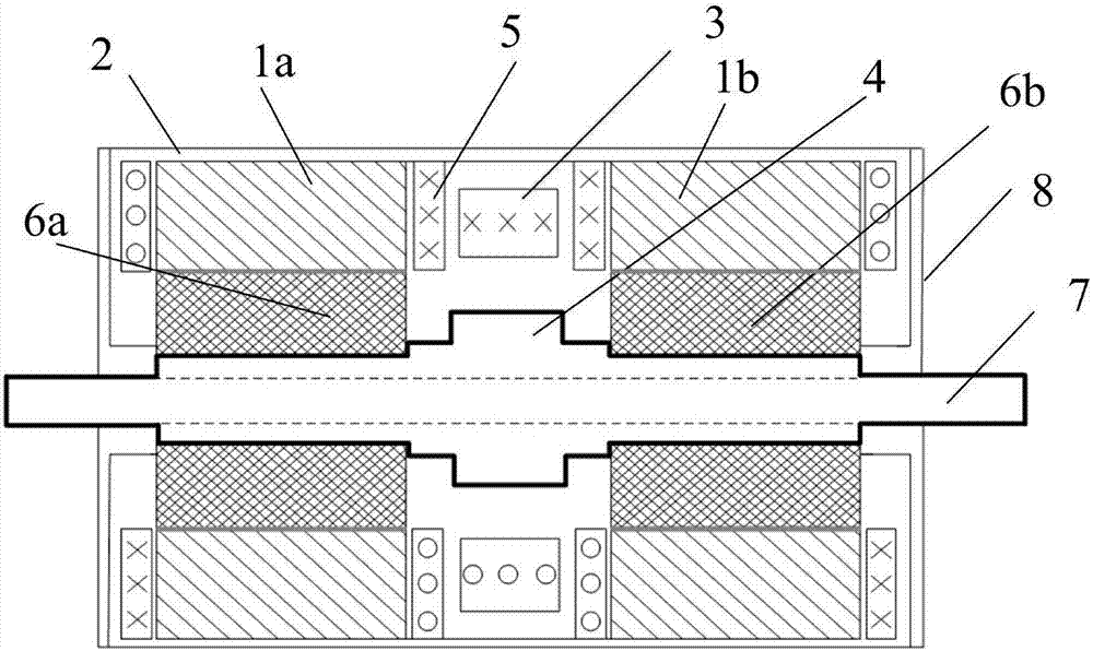
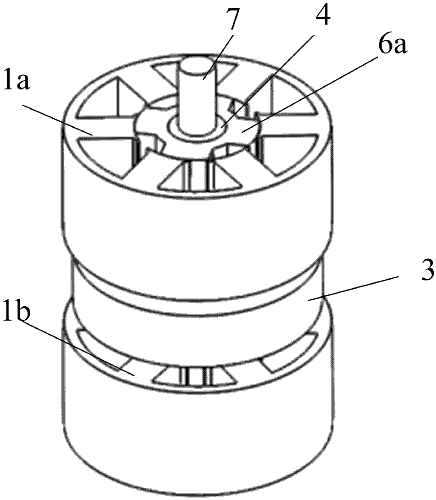
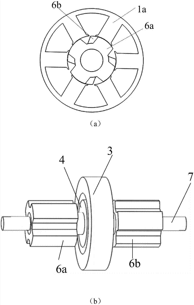
The invention discloses an axial electrical excitation composite rotor circumferential misplacement reluctance motor control system and method, and belongs to the technical field of electrical appliance automatic control. The axial electrical excitation composite rotor circumferential misplacement reluctance motor control system comprises a DSP (Digital Signal Processor), a position sensor, a speed sensor, a current sensor, a level reversion chip, a three-phase asymmetrical half-bridge power converter, a driving circuit and the like. A controlled motor comprises a motor revolving shaft, a magnetic conductive material, a central electric excitation coil, a stator salient pole, a rotor salient pole and the like. The method comprises the following steps: generating a new PWM (Pulse-Width Modulation) duty ratio according to data transmitted by the position sensor, the speed sensor and the current sensor through the DSP; and adjusting current of a three-phase winding or adjusting current of the electric excitation coil. The electric excitation coil is arranged between two groups of stators, and a rotor circumferential misplacement structure is adopted for running, so that crest connection of torque between two sets of stators and rotors is realized effectively. Double-closed-loop PI (Proportional-Integral) control is adopted, so that the dynamic response speed and interference resistance of the control system are improved greatly, and efficient continuous speed adjustment control of a motor can be realized easily.

Description

technical field [0001] The invention belongs to the technical field of electric appliance automation control, and in particular relates to a control system and method for an axial electric excitation compound rotor circumferential displacement reluctance motor. Background technique [0002] Torque ripple and loud noise are two factors that limit the application of electric motors. Torque ripple means that within a commutation cycle of the motor, the difference between the maximum value and the minimum value of the output torque is too large, causing the motor to vibrate. The torque ripple is more obvious when the motor is far away from the design point, especially in electric vehicles, textiles, etc. And other industries that require high motor output torque. There are two main reasons for the torque ripple: one is that the special double-salient pole structure of the motor determines that there must be a large torque ripple, especially at the position where the stator and ...

Claims


Application Information

Patent Timeline
Patent Type & Authority Applications(China)
IPC IPC(8): H02P25/092H02P25/098H02K16/00
CPCH02K16/00H02P25/092H02P25/098
Inventor 刘爱民李博娄家川高智超任达孙鹏李家尧韦有帅
Owner SHENYANG POLYTECHNIC UNIV
Learn More