Jet-flow tube electro-hydraulic servo valve driven by piezoelectric ceramic

A piezoelectric ceramic drive, piezoelectric ceramic technology, applied in servo motor components, fluid pressure actuation devices, fluid pressure actuation system components, etc., can solve the problem of large inertia of the jet tube, slow dynamic response, and complex torque motor processing technology and other problems, to achieve the effect of high control accuracy, fast dynamic response, and improved dynamic response speed and control accuracy

Active Publication Date: 2017-12-05
YANSHAN UNIV
View PDF11 Cites 6 Cited by
  • Summary
  • Abstract
  • Description
  • Claims
  • Application Information

AI Technical Summary

Problems solved by technology

Although the jet tube servo valve is widely used for its high reliability and high pollution resistance, its disadvantage is that the jet tube has a large inertia, resulting in a slow dynamic response; the processing technology of the torque motor is complicated and difficult to process

Method used


Image

  • Jet-flow tube electro-hydraulic servo valve driven by piezoelectric ceramic
  • Jet-flow tube electro-hydraulic servo valve driven by piezoelectric ceramic
  • Jet-flow tube electro-hydraulic servo valve driven by piezoelectric ceramic

Examples


Embodiment 1

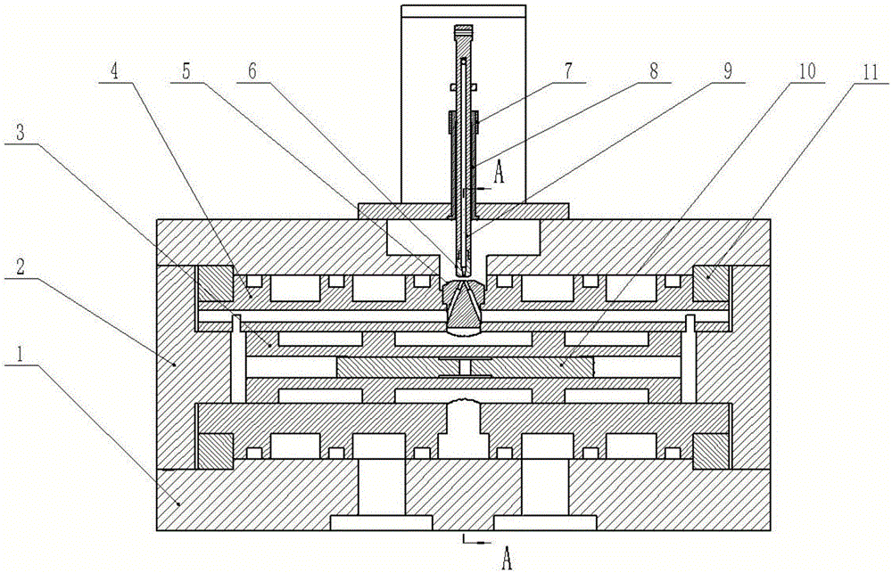
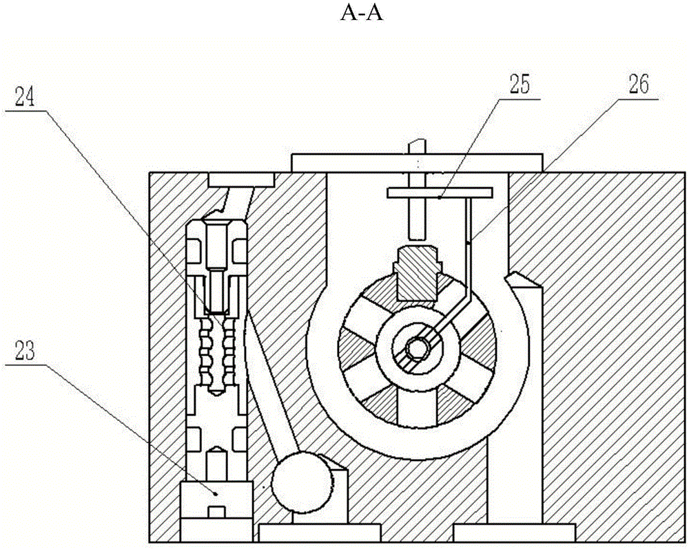
[0021] in figure 1 , figure 2 , image 3 As shown in the schematic diagram of the present invention, the piezoelectric ceramic driven jet tube electro-hydraulic servo valve includes a main valve, a piezoelectric ceramic pre-stage, and a feedback rod. The piezoelectric ceramic pre-stage is fixed with the main valve body by screws, and the nozzle of the jet tube is aligned with the receiver. One end of the feedback rod is connected with the main valve core through the clamping screw, and the other end of the feedback rod is connected with the jet Pipe connection.

[0022] The main valve includes a valve body 1, a valve sleeve 4, a valve core 3, a receiver 5, a clamping screw 10, a locking ring 11, an oil filter 24, a plug 23, and an end cover 2. The inner hole of the valve body 1 is provided with a valve sleeve 4, and the inner hole of the valve body 1 is provided with a locking ring 11 for fixing the valve sleeve 4. A sealing ring is arranged in the upper sealing groove of the v...

Embodiment 2

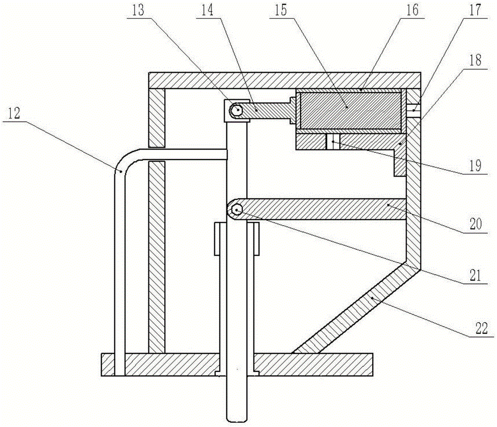
[0028] in figure 1 , figure 2 , Figure 4 As shown in the schematic diagram of the present invention, the piezoelectric ceramic driven jet tube electro-hydraulic servo valve includes a main valve, a piezoelectric ceramic pre-stage, and a feedback rod. The piezoelectric ceramic pre-stage is fixed with the main valve body by screws, and the nozzle of the jet tube is aligned with the receiver. One end of the feedback rod is connected with the main valve core through the clamping screw, and the other end of the feedback rod is connected with the jet Pipe connection.

[0029] The main valve includes a valve body 1, a valve sleeve 4, a valve core 3, a receiver 5, a clamping screw 10, a locking ring 11, an oil filter 24, a plug 23, and an end cover 2. The inner hole of the valve body 1 is provided with a valve sleeve 4, and the inner hole of the valve body 1 is provided with a locking ring 11 for fixing the valve sleeve 4. A sealing ring is arranged in the upper sealing groove of the...


PUM


Abstract

Disclosed is a jet-flow tube electro-hydraulic servo valve driven by piezoelectric ceramic. The servo valve comprises a main valve, a piezoelectric ceramic pre-stage and a feedback rod. The piezoelectric ceramic pre-stage is fixed with the main valve body through screws, and it is ensured that a jet-flow tube nozzle is aligned with a receiver; one end of the feedback rod is connected with a main valve core through a clamping screw, and the other end of the feedback rod is connected with a jet-flow tube. According to the jet-flow tube electro-hydraulic servo valve driven by the piezoelectric ceramic, the displacement of piezoelectric ceramic stacks is amplified through the adoption of the lever principle, so that it is possible to use piezoelectric ceramic to drive the jet-flow tube; by taking the advantages of the piezoelectric ceramic materials that the dynamic responding speed and the control precision are high, the dynamical responding speed and control precision of the jet-flow servo valve are improved; the piezoelectric ceramic materials have no electromagnetic interference and are simple and reliable without electromagnetic shielding.

Description

Technical field [0001] The invention relates to a servo valve, belonging to the technical field of jet tube type electro-hydraulic servo valves. Background technique [0002] The electro-hydraulic servo valve is the core component of the electro-hydraulic servo system. Its performance directly determines and restricts the control precision, response characteristics, reliability and life of the electro-hydraulic servo mechanism. At present, the most commonly used electro-hydraulic servo valves are jet tube servo valves and nozzle flapper servo valves. Compared with the nozzle flapper servo valve, the jet tube servo valve is widely used in aerospace, shipbuilding, military industry and various industrial control fields due to its outstanding advantages such as high pollution resistance, high reliability, and high resolution. [0003] The traditional jet tube servo valve is mainly composed of a torque motor, a jet tube amplifier, a power slide valve, a feedback spring assembly and a ...

Claims


Application Information

Patent Timeline
Patent Type & Authority Applications(China)
IPC IPC(8): F15B13/02F15B21/04
CPCF15B13/02F15B21/041
Inventor 胡建军杨泽贺孔祥东
Owner YANSHAN UNIV
Why Eureka
Try Eureka