Cam preparation method and cam type four-cylinder single-action reciprocating pump

A cam and cam two technology, applied in the direction of pumps, piston pumps, mechanical equipment, etc., can solve the problems of difficulty in ensuring the synchronization of the three cams, increasing the difficulty of mass production of the cams, accelerating the fatigue damage of the cams, etc., and achieving torque reduction , Improve self-priming performance, eliminate the effect of flow and pressure pulsation

Inactive Publication Date: 2012-08-15
CHINA UNIV OF GEOSCIENCES (WUHAN)
View PDF3 Cites 10 Cited by
  • Summary
  • Abstract
  • Description
  • Claims
  • Application Information

AI Technical Summary

Problems solved by technology

[0003] A. The profile curve adopted by a single cam is calculated according to the uniform acceleration-uniform speed-uniform deceleration motion of the piston. The radius of curvature of this profile has a sudden change, which causes the stress concentration at the sudden change point and accelerates the fatigue damage of the cam.
Although optimization of the curve can eliminate sudden changes in the radius of curvature in the "Constant Flow Pump Cam Curve Optimization Design" published in the fourth issue of "Mechanical Transmission" in 2001, the motion law adopted by the optimized curve equation is extremely complicated, which increases the cam Difficulty in mass production
[0004] B. The cam pump adopts three cams in pairs to form a constant flow rate with a phase difference of 2π / 3. During the operation of the pump, the key connection between the cam and the power output shaft is worn, and the synchronization of the three cams is difficult to guarantee.

Method used


Image

  • Cam preparation method and cam type four-cylinder single-action reciprocating pump
  • Cam preparation method and cam type four-cylinder single-action reciprocating pump
  • Cam preparation method and cam type four-cylinder single-action reciprocating pump

Examples


Embodiment Construction

[0037] The present invention is described in detail below:

[0038] The prepared cam on the four-cylinder single-acting reciprocating pump used for drilling engineering, its preparation steps:

[0039] A kind of preparation method of cam, its steps:

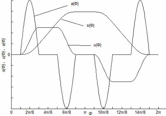
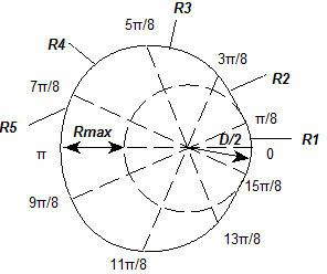
[0040] 1) Determine the upper contour line of the cam, the steps are:

[0041] (1) Determine the contour radius R1 corresponding to the cam between 0 and π / 8 of the cam rotation, and the distance is a constant: 78.54mm;

[0042] (2) Determine the contour radius R2 corresponding to the cam between π / 8 and 3π / 8 of cam rotation:

[0043] Substitute ф=π / 8~3π / 8 into the following formula for calculation: =78.54~98.17 mm;

[0044] (3) Determine the contour radius R3 corresponding to the cam between 3π / 8~5π / 8 of the cam rotation,

[0045] Substitute ф=3π / 8~5π / 8 into the following formula for calculation: =98.17 ~137.44mm;

[0046] (4) Determine the contour radius R4 corresponding to the cam between 5π / 8~7π / 8 of the cam rotation...


PUM


Abstract

The invention relates to a cam preparation method and a cam type four-cylinder single-action reciprocating pump. The cam preparation method comprises the following steps of: determining an upper contour line of contour radius vectors from R1 to R5 corresponding to the cam which rotates between 0 and Pi, wherein a lower contour line is symmetric with the upper contour line; copying the upper contour line to be a whole contour line of the cam; and lofting and forming. The cam type four-cylinder single-action reciprocating pump consists of four single-action cylinders, pistons of the single-action cylinders, piston rods connected with the pistons, intermediate rods connected with the piston rods, a transmission shaft, the cam arranged on the transmission shaft, a resetting framework arranged outside the cam, a guide framework arranged outside the resetting framework, bearings for enabling the transmission shaft to be fixed on the guide framework and a motor connected with the transmission shaft, wherein the cam comprises a cam I and a cam II which are prepared by the preparation method and have the same shape; and the cam I and the cam II are arranged on the transmission shaft in a manner of forming a 90-degree phase difference. According to the cam type four-cylinder single-action reciprocating pump, the reciprocating pump can output fluid constantly without any fluctuation, and the self-suction performance is high.

Description

technical field [0001] The invention relates to a preparation method of a cam and a cam type reciprocating pump, in particular to a preparation method of a cam and a cam type four-cylinder single-acting reciprocating pump. Background technique [0002] The reciprocating pump is one of the most commonly used core equipment in drilling construction, and is widely used in circulating drilling fluid and pressure grouting during drilling. The power end of the traditional reciprocating pump generally adopts a crank-connecting rod mechanism, and the reciprocating motion of the piston is realized by converting the rotary motion of the crank through connecting rods, crossheads and other mechanisms. The quasi-simple harmonic motion of the crank-link mechanism drives the piston to perform simple harmonic motion. Therefore, the output displacement and pressure of each cylinder of the reciprocating pump are pulsating. In order to eliminate this pulsation as much as possible, an air bag ...

Claims


Application Information

Patent Timeline
Patent Type & Authority Applications(China)
IPC IPC(8): B23P17/00F04B9/04
Inventor 王安德袁春娥李均山潘义辉
Owner CHINA UNIV OF GEOSCIENCES (WUHAN)
Why Eureka
Try Eureka