Guide sleeve, guide sleeve structure and oil cylinder

A technology of guide sleeves and oil cylinders, applied in the direction of fluid pressure actuation devices, etc., which can solve the problems of large load bearing of snap ring retaining rings, lower assembly reliability, and increased processing difficulty, so as to improve reliability, reduce difficulty, and eliminate bolts The effect of uneven force

Active Publication Date: 2012-08-15
SANY HEAVY IND CO LTD (CN)
View PDF6 Cites 8 Cited by
  • Summary
  • Abstract
  • Description
  • Claims
  • Application Information

AI Technical Summary

Problems solved by technology

[0005] 1) When the retraction friction of the piston rod is large, the retaining ring of the snap ring bears a large load, and the screws fixing the snap ring are easily damaged;
[0006] 2) In order to avoid damage, it is necessary to increase the size of related parts to improve strength and increase the number of screws, but this will increase the difficulty of processing and reduce the reliability of assembly

Method used


Image

  • Guide sleeve, guide sleeve structure and oil cylinder
  • Guide sleeve, guide sleeve structure and oil cylinder
  • Guide sleeve, guide sleeve structure and oil cylinder

Examples


Embodiment Construction

[0034] In order to understand the above-mentioned purpose, features and advantages of the present invention more clearly, the present invention will be further described in detail below in conjunction with the accompanying drawings and specific embodiments.

[0035] In the following description, many specific details are set forth in order to fully understand the present invention. However, the present invention can also be implemented in other ways different from those described here. Therefore, the protection scope of the present invention is not limited by the specific details disclosed below. EXAMPLE LIMITATIONS.

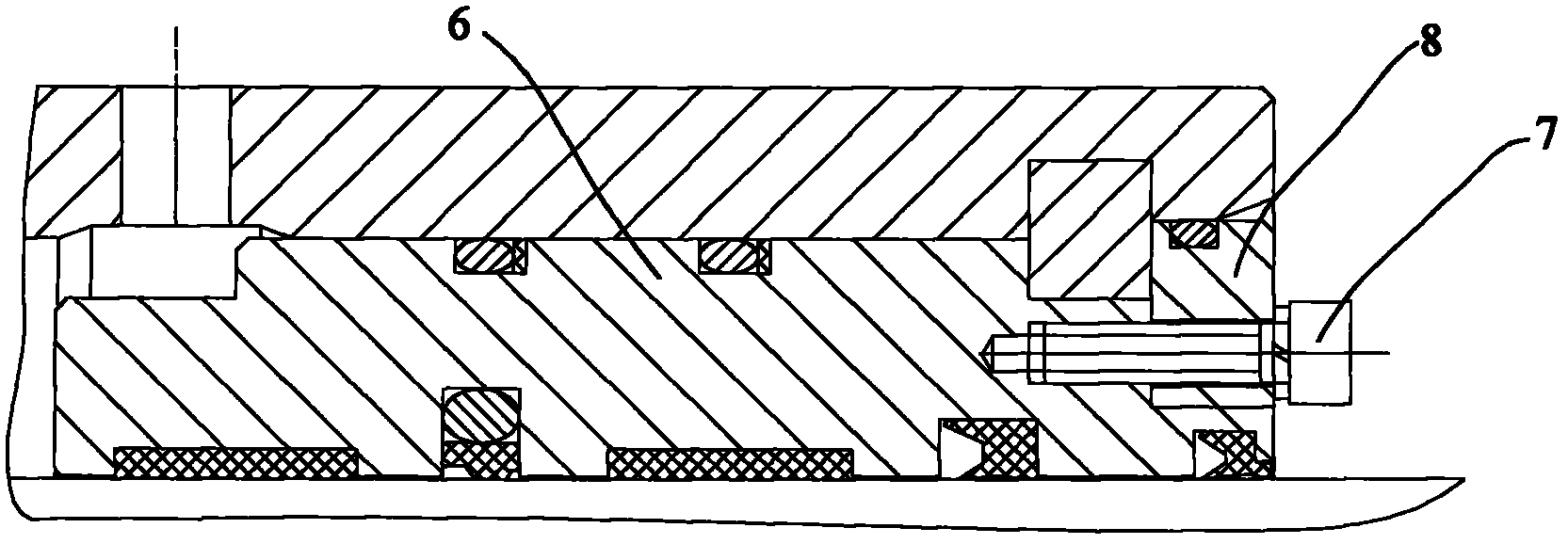
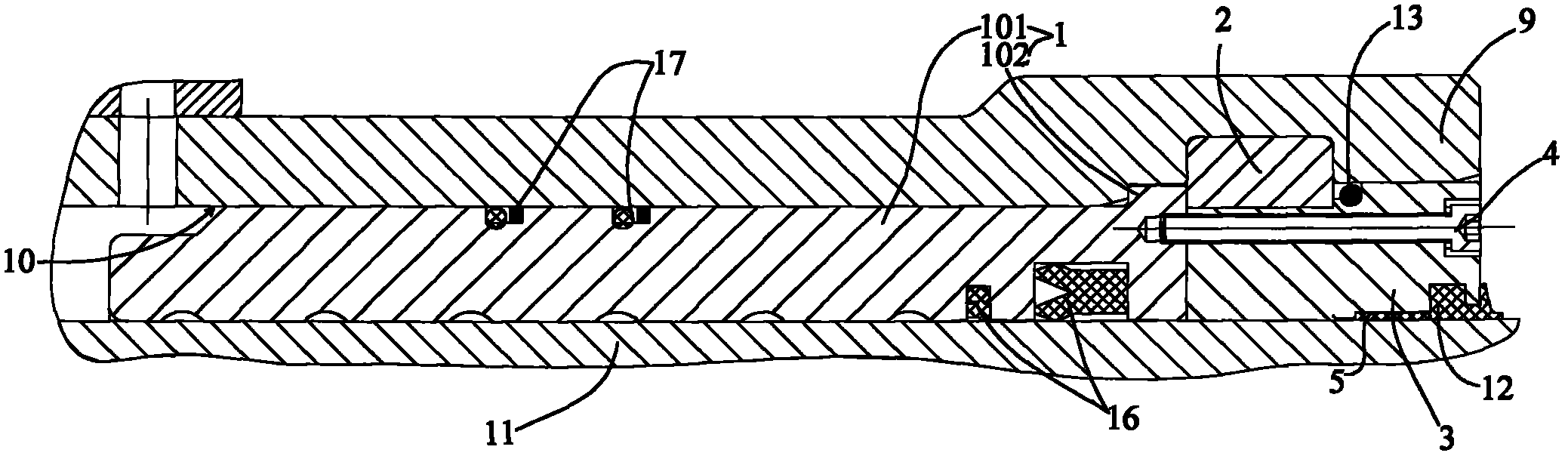
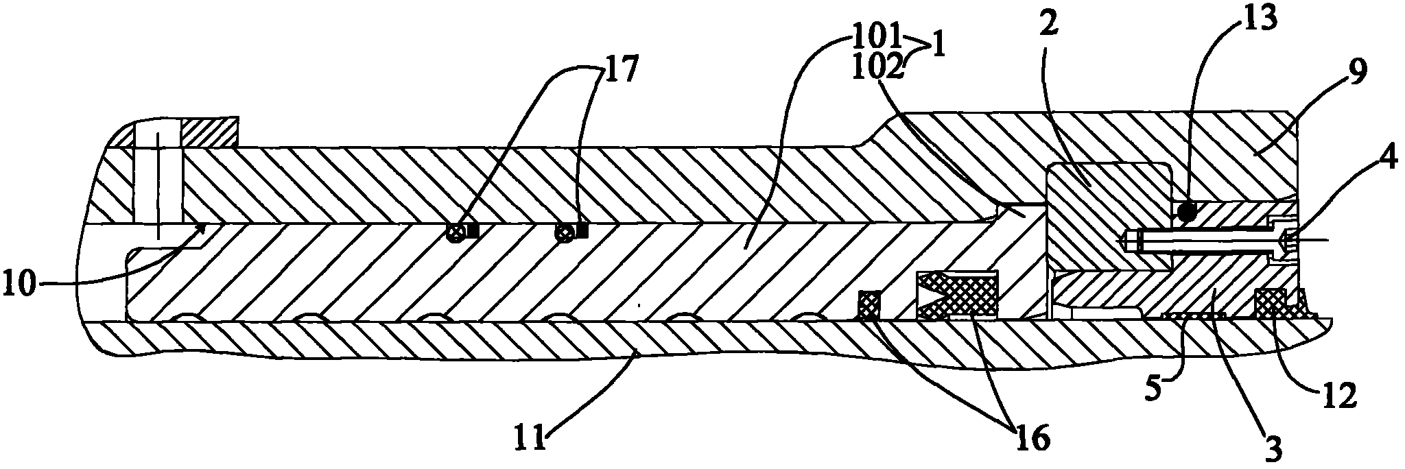
[0036] Figure 2 to Figure 4 It is a schematic diagram of guide sleeve structures installed in a cylinder according to different embodiments of the present invention.

[0037] Such as Figure 2 to Figure 4 As shown, the present invention provides a guide sleeve 1, which is arranged on the inner wall 10 of the cylinder mouth 9 of the oil cylinder, and the outer...


PUM


Abstract

The invention provides a guide sleeve which is arranged on the inner wall of a cylinder barrel hole of an oil cylinder; and a first boss matched with the inner wall is arranged on a guide sleeve body at the outer side of the end close to the cylinder hole. Furthermore, the invention also provides a guide sleeve structure of the guide sleeve, and the oil cylinder comprising the guide sleeve structure. Due to the technical scheme, the strength of the structure used for preventing the guide sleeve from sliding towards the interior of a cylinder barrel can be improved; and meanwhile, the number of screws can be reduced, and the assembly difficulty is lowered.

Description

technical field [0001] The invention relates to the field of guide sleeve structures, in particular to a guide sleeve, a guide sleeve structure and an oil cylinder. Background technique [0002] At present, most hydraulic cylinders adopt the following guide sleeve structures: threaded guide sleeves, threaded glands, and ordinary key. A guide sleeve is provided between the front end of the cylinder and the piston rod, which is mainly used to seal and support the piston rod. It needs to be sealed and fixed with the cylinder. The fixing method is required to be reliable and easy to process and assemble. [0003] The key guide sleeve structure in the existing related art is as follows: figure 1 As shown: the guide sleeve 6 is subjected to the force of the piston rod in the horizontal direction. When the piston rod moves to the left, the friction force between the guide sleeve 6 and the piston rod is completely borne by the bolt 7 and the retaining ring 8. [0004] figure 1 Th...

Claims


Application Information

Patent Timeline
Patent Type & Authority Applications(China)
IPC IPC(8): F15B15/20F15B15/14
Inventor 陈兵兵李才刘昆
Owner SANY HEAVY IND CO LTD (CN)
Why Eureka
Try Eureka