Large unsaturated seepage physical simulator for soil in aerated zone

A technique of physical simulation and vadose zone, applied in soil material testing, material inspection products, etc., can solve the problem that the migration process has a large impact, cannot simulate the seepage and solute migration in unsaturated zones, and it is difficult to meet the boundary conditions of the model, etc. Problems, to achieve the effect of improving hands-on ability and wide application prospects

Inactive Publication Date: 2012-08-15
CHINA UNIV OF GEOSCIENCES (WUHAN)
3 Cites 37 Cited by

AI-Extracted Technical Summary

Problems solved by technology

[0003] For example, the indoor one-dimensional soil column developed by predecessors can simulate unsaturated seepage in vadose zone soil and one-dimensional hydrodynamic dispersion, but the instrument can only simulate one-dimensional flow; another example is the groundwater column developed by predecessors. Pollution simulation tank, the device can simulate the solute migration process of multiple aquifers, and can also simulate two-dimensional soil water flow, but its size is too small to completely simulate the actual field situation, and it cannot perform simultaneous online monitoring of multiple parameters
[0004] According to previous studies, the current physical simulation dev...

Abstract

The invention provides an unsaturated seepage physical simulator for soil in an aerated zone. The unsaturated seepage physical simulator comprises a tested soil tank, a supplementing and draining system and a measuring system, the tested soil is contained in the tested soil tank, the supplementing and draining system consists of a lateral supplementing and draining unit, a bottom supplementing and draining unit and a top supplementing and draining unit, the lateral supplementing and draining unit consists of a water supplementing device and a water draining device which are respectively mounted on two side walls of the tested soil tank, the top supplementing and draining unit consists of a rainfall device, an evaporation device and an accumulated water infiltration device, and the measuring system comprises a soil solute measuring unit, a soil moisture measuring unit, a soil water potential measuring unit and an underground water level measuring unit. The large unsaturated seepage physical simulator for the soil in the aerated zone not only can sufficiently simulate various conditions of soil in the aerated zone, but also is convenient in measurement and low in errors.

Application Domain

Technology Topic

Image

  • Large unsaturated seepage physical simulator for soil in aerated zone
  • Large unsaturated seepage physical simulator for soil in aerated zone
  • Large unsaturated seepage physical simulator for soil in aerated zone

Examples

  • Experimental program(1)

Example Embodiment

[0026] The present invention will be described in detail below in conjunction with the accompanying drawings.
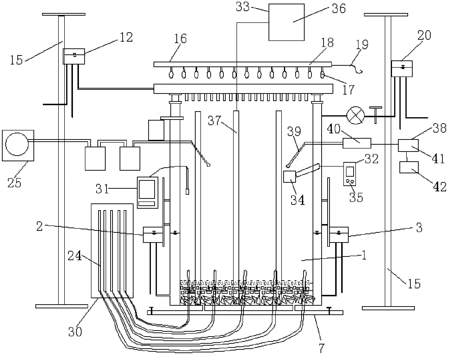
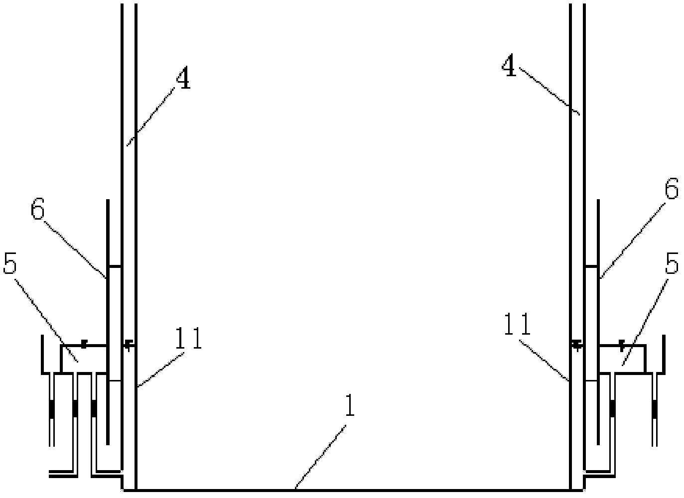
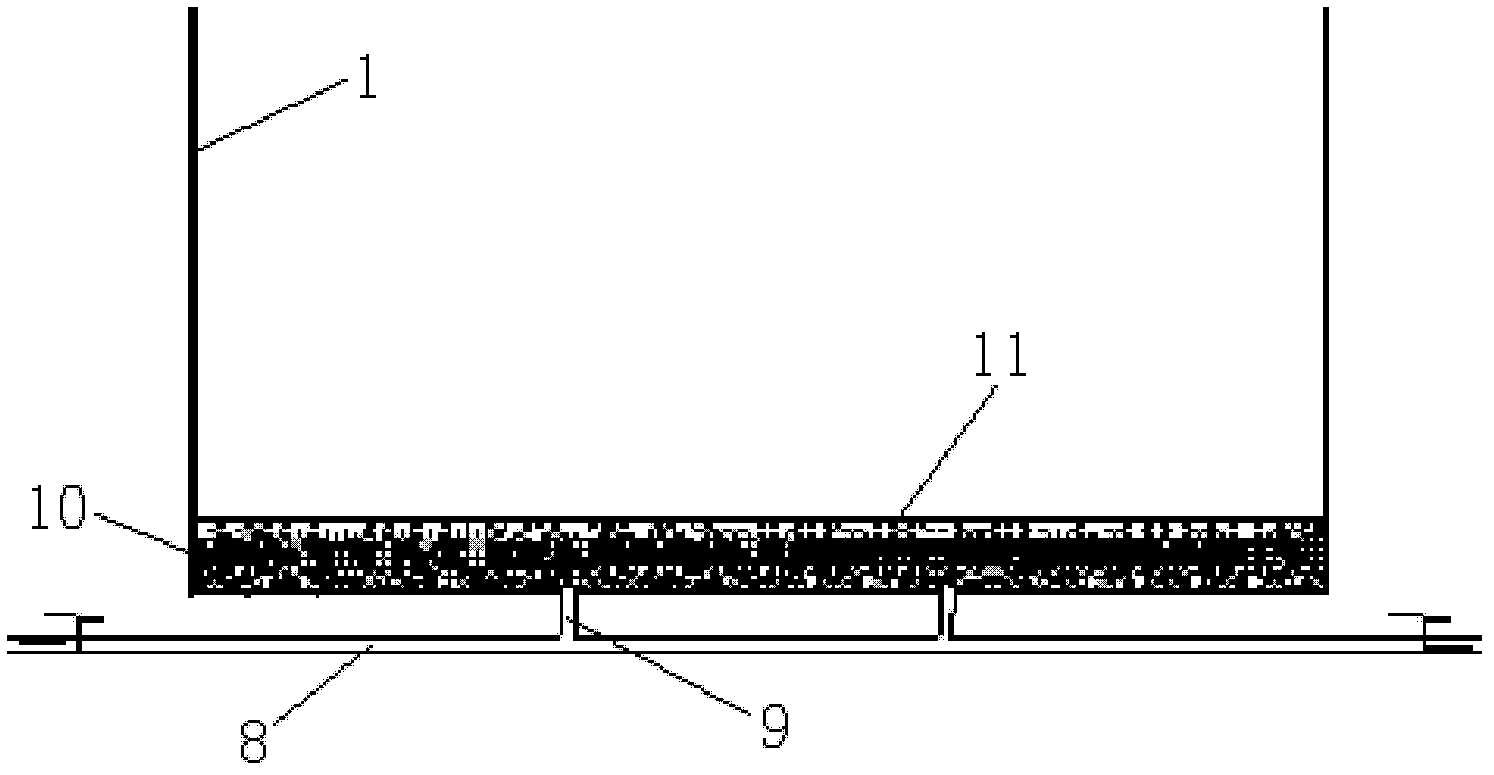
[0027] The schematic diagram of the overall structure of the large-scale vadose zone soil unsaturated seepage physical simulation device provided by the present invention is as follows: figure 1 As shown, it includes at least the test soil tank 1, the supplementary drainage system and the measurement system. The test soil tank 1 is in the shape of a cuboid and is welded by 0.5cm thick iron plates. The length, width and height of the cuboid-shaped test soil tank are respectively 3m, 1m, 4m. The test soil tank 1 is filled with test soil. The test medium is loose sediment from the floodplain of the Yangtze River. The impurities in the test soil are screened out, and then the soil tank is loaded into layers and compacted. The thickness of each layer is 10-20 cm. The thickness is 3.6m.
[0028] The supplementary drainage system includes a lateral supplementary drainage unit, a bottom supplementary drainage unit 7 and a top supplementary drainage unit. The lateral supplementary drainage unit is composed of a water supply device 2 and a drainage device 3 respectively installed on the two side walls of the test soil tank 1. Its structure like figure 2 shown. Wherein the water replenishment device 2 and the drainage device 3 all include a water tank 4 and a water tank 5, and the water tank 5 is installed on the outer wall of the test soil tank 1 by a lifting frame 6 and its height can be adjusted, and the water tank 5 communicates with the water tank 4 through a water pipe; The lifting frame 6 is fixed on the side wall of the test soil tank 1, the water tank 4 is narrow and long, and is formed by the inner wall of the test soil tank 1 and the filter screen 11, and the inner side of the water tank 4 is in contact with the test soil through the filter screen 11 . The water tank on the left is used to simulate the water supply canal, and the water tank on the right is used to simulate the drainage canal; the water tank 5 on the left is used to stabilize the water level of the water supply canal, and the water tank 5 on the right is used to stabilize the water level of the drainage canal; the lifting frame 6 can be freely lifted The water tank 5 is used to change the water level on both sides of the test soil tank 1; the filter screen 11 mainly ensures that the soil structure is not destroyed when the water enters and discharges the soil to ensure the stability of the soil.
[0029] The structure of the bottom replenishment unit 7 is as image 3As shown, it includes a water pipe 8 and a connecting pipe 9. The two ends of the water pipe 8 are respectively provided with a water inlet switch and a water outlet switch. At least one connecting pipe 9 is provided. In this embodiment, there are two connecting pipes 9. One end of the connecting pipe 9 communicates with the water pipe 8, and the other end of the connecting pipe 9 communicates with the bottom of the test soil tank 1; the bottom replenishing unit 7 is also provided with a balance layer 10, and the balance layer 10 is located at the bottom of the test soil tank 1, A filter screen 11 is arranged above the balance layer 10, and the balance layer 10 contacts the test soil through the filter screen 11. The balance layer 10 is composed of sand, and the particle size of the sand gradually increases from top to bottom. The function of the balance layer 10 is to ensure the horizontal rise and fall of the water level when replenishing the water. The balance layer 10 is composed of coarse sand, gravel, and gravel from top to bottom. The thickness of the gravel layer is 10 cm, and the particle size of the gravel is 2 to 10 cm. The thickness of the gravel layer is 5cm, and the particle size of the gravel is 0.2-2cm; the thickness of the coarse sand layer is 5cm, and the particle size of the coarse sand is 0.05-0.2cm. When both the water inlet switch and the drain switch are turned off, the bottom replenishment and drainage unit 7 does not perform replenishment and drainage; when the water inlet switch is turned on and the drain switch is turned off, the bottom replenishment and drainage unit 7 enters water; when the water inlet switch is turned off and the drain switch is turned on , the bottom replenishing unit 7 drains water. The effect of filter screen 11 is not to destroy soil structure when moisture enters and discharges soil.
[0030] The top supplementary drainage unit comprises a rainfall device 12, an evaporation device 16, and a water infiltration device 20, and the structure of the rainfall device 12 is as follows: Figure 4 As shown, it includes a rainfall water tank 14 and a rainfall device 13 covering the top of the test soil tank 1, and the rainfall water tank 14 communicates with the rainfall device 13 through a water pipe. Rainfall device 13 is made of plexiglass, and its width is 1m, and length is 3m. 7500 water outlet needles are uniformly arranged on the base plate of the raining device 13; the raining device 12 also includes a lifting rod 15, and the rainfall water tank 14 is installed on the lifting rod 15 and the height of the rainfall water tank 14 can be adjusted. The function of the rainfall water tank 14 is to provide a stable water flow for the rainwater device 13, and adjust different water surface heights by adjusting the height of the rainfall water tank 14 on the elevating rod 15, so as to achieve the purpose of changing the intensity of rainfall.
[0031] The evaporation device 16 includes a lamp holder 18 located above the test soil tank 1, a wire 19 and an infrared lamp 17 installed on the lamp holder 18; the evaporation device 16 mainly simulates the excretion conditions under different evaporation intensities on the soil surface. The infrared lamp 17 is used to simulate solar radiation, and the radiation intensity is regulated by an adjustable voltage transformer.
[0032] The structure of ponded water infiltration device 20 is as Figure 5 As shown, it includes lifting rod 15, infiltration water tank 21, flow meter 22, infiltration switch and measuring cylinder 23. The infiltration water tank 21 is installed on the lifting rod 15 and its height can be adjusted. The infiltration water tank 21 passes through the water pipe and the test soil tank The seepage inlet on 1 is connected, and the water pipe is provided with a flow meter 22 and an infiltration switch. The measuring cylinder 23 is located below the seepage outlet on the test soil tank 1, and both the seepage inlet and the seepage outlet are located above the upper surface of the test soil. . The stagnant water infiltration device 20 mainly simulates flood irrigation replenishment conditions, and its function is to establish a water layer with a stable water depth on the upper surface of the test soil, and can continuously supply water and measure the amount of seepage. The flowmeter 22 is used to measure the influent flow; the effect of the infiltration water tank 21 is to provide a stable water level to ensure that the water flows into the test soil tank 1 stably, while ensuring the accuracy and reliability of the flowmeter 22; through the lifting rod 15 The height of the infiltration tank 21 can be adjusted to adjust the flow rate of water; the measuring cylinder 23 is used to measure the overflow when flooding.
[0033] The measurement system includes a soil solute measurement unit, a soil moisture measurement unit, a soil water potential measurement unit 38 and a groundwater level measurement unit 30 . Described soil solute measuring unit comprises solute component measuring device and solution concentration measuring device, and solute component measuring device is mainly made up of soil solution sampler 25 and chemical analysis instrument; The structure of soil solution sampler 25 is as follows Image 6 As shown, it is composed of a suction cup 26, a sampling bottle 27, a buffer bottle 28 and a vacuum pump 29, and the four are connected sequentially through a silicone tube; the suction cup 26 is composed of a ceramic head and a polyester tube, and the ceramic head is located inside the test soil , the polyester tube passes through the side wall of the test soil tank 1 and communicates with the silicone tube. In order to prevent moisture from seeping out around the sampler, the contact position between the polyester tube and the test soil tank 1 is sealed with a rubber ring; in this embodiment, the poly A total of 30 ester pipes are installed. When sampling, the vacuum pump 29 applies a certain negative pressure (usually ≤ 50kPa) to the system. When the capillary pressure in the suction cup 26 is less than the soil capillary pressure, the solution in the test soil is sucked into the suction cup 26 until the two are equal. The soil solution obtained in the sampling bottle 27 is taken out, and its composition is determined by a chemical analysis instrument.
[0034] The solution concentration measuring device consists of a salinity sensor located inside the test soil and a conductivity meter 31 connected to the salinity sensor through wires. The contact salinity sensor is pre-embedded in the test soil, and the conductivity value is measured according to the different conductivity of the soil solution with different concentrations. After conversion of the calibration equation, the result of the concentration of the soil solution can be given. In this embodiment, the salinity sensors are embedded with the layered filling of the test soil, and a total of 60 sensors are embedded. When measuring, connect the lead wire to the conductivity meter 31, read the value from the conductivity meter 31, and convert it through the calibration formula to obtain the solution concentration of the test soil at the location of the salinity sensor.
[0035] The soil moisture measuring unit is made up of resistance method measuring device 32 and neutron scattering method measuring device 33, wherein resistance method measuring device 32 is made up of gypsum block 34 and moisture measuring instrument 35, and gypsum block 34 is evenly distributed in the test soil, is equipped with 48 pieces, moisture meter 35 is connected with gypsum block 34 by wire; Moisture meter 35 must be calibrated before use. During measurement, the gypsum block 34 to be measured is connected to the moisture meter 35, and the soil water content at the location of the gypsum block 34 can be obtained through calculation and transformation.
[0036] The neutron scattering method measuring device 33 comprises a soil moisture neutron meter 36 and a measuring tube 37. The measuring tube 37 is provided with three, and the measuring tube 37 is positioned before filling the test soil. The three measuring tubes 37 are arranged in a row and evenly distributed in the In the test soil tank 1, the length of the measuring pipe 37 is 4 m. On-site calibration is carried out before measurement. During measurement, the soil moisture neutron meter 36 is turned on, and the soil moisture neutron meter 36 is used to obtain measurement results.
[0037] The function of the soil water potential measurement unit 38 is mainly to monitor the change of pore water pressure of the soil in the soil tank during the test. Soil water potential measurement unit 38 comprises tensiometer tube 39, electronic tensiometer 40, pressure sensor 41 and data acquisition instrument 42, tensiometer tube 39 is provided with 60 altogether, and the first section of tensiometer tube 39 passes the side of test soil tank 1 The wall is buried in the test soil, and the first end of the tensiometer tube 39 is a porous ceramic head, and the tail end of the tensiometer tube 39 is provided with two connection ports, one of which is connected to the pressure sensor 41, and the pressure sensor 41 is connected to the pressure sensor 41. The data acquisition instrument 42 is connected; the other connection port is provided with a rubber plug, and the probe on the electronic tensiometer 40 can pass through the rubber plug and enter the tensiometer tube 39 to directly measure the tension. The work of the soil water potential measuring unit 38 among the present invention is similar to the principle that the plant root system absorbs moisture from the soil. When the moisture in the soil decreases and the water potential decreases, the moisture in the tensiometer tube 39 embedded in the soil will flow from the porous The ceramic head oozes out, and now a certain degree of vacuum is formed in the tensiometer tube 39, and by measuring the vacuum degree in the tensiometer tube 39, the variation of the water potential in the test soil can be reflected. When measuring the test soil water potential, the probe of the electronic tensiometer 40 is inserted into the rubber plug into the tensiometer to measure the measured value. In addition, the pressure sensor 41 is connected to the data acquisition instrument 42, and the data acquisition instrument 42 can automatically record the water potential of each position in the soil according to the set time interval. If the data acquisition instrument 42 is connected to the computer again, the soil water potential at different positions in the soil tank can be monitored in real time on the computer.
[0038] Groundwater level measuring unit 30 is used for determining the head distribution condition in test soil tank 1, and groundwater level measuring unit 30 comprises 5 piezometric tubes 24, and piezometric tube 24 is evenly installed in the bottom of test soil tank and the bottom of piezometric tube 24 One end is located inside the test soil tank 1. In the present invention, the water head distribution in the test soil tank 1 can also be observed by observing the water level of the water tank 5 in the lateral supplementary drainage unit.

PUM

no PUM

Description & Claims & Application Information

We can also present the details of the Description, Claims and Application information to help users get a comprehensive understanding of the technical details of the patent, such as background art, summary of invention, brief description of drawings, description of embodiments, and other original content. On the other hand, users can also determine the specific scope of protection of the technology through the list of claims; as well as understand the changes in the life cycle of the technology with the presentation of the patent timeline. Login to view more.

Similar technology patents

Electric broiler of children's toy electric oven

InactiveCN104258579AImprove hands-on abilityToysRoasters/grillsEngineeringBroiler chick
Owner:DONGGUAN XUKE ELECTRONICS PROD

Toy shovel for early intelligence development of infants

InactiveCN109794072ALittle elasticityImprove hands-on abilityToysTeaching apparatusAgricultural engineeringSunlight
Owner:XIAN MEIYU INFORMATION TECH

Intelligent induction pet toy

Owner:江都区小纪镇恺胜体育用品厂

Intelligence building block

PendingCN111672141AImprove hands-on abilityPromote brain developmentToysStructural engineeringBrain development
Owner:周晓青

Classification and recommendation of technical efficacy words

  • Broad application prospects
  • Improve hands-on ability

Method for preparing cellulose water-based solution by stalk

InactiveCN101456958ABroad application prospectsReduce the amount of alkali usedPaper material treatmentBiomassSeparation process
Owner:UNIV OF SCI & TECH OF CHINA

Teaching and experiment instrument of automatic control theory

InactiveCN101650884AIncrease flexibilityImprove hands-on abilityTeaching apparatusAutomatic controlExperiment control
Owner:ZHONGBEI UNIV

Typical mechanism motion analysis modular teaching device

InactiveCN104504989AImprove understanding and hands-on abilityImprove hands-on abilityEducational modelsModularityEngineering
Owner:TIANJIN UNIV
Why Eureka
Try Eureka