
Passive safety shell cooling system

A passive containment and cooling system technology, applied in the field of cooling systems, can solve problems such as cooling water freezing, and achieve the effects of maintaining integrity, reducing volume, and preventing hydrogen explosion

Active Publication Date: 2012-08-15
HARBIN ENG UNIV
View PDF5 Cites 22 Cited by
  • Summary
  • Abstract
  • Description
  • Claims
  • Application Information

AI Technical Summary

Problems solved by technology

This creates problems related to earthquakes and freezing of cooling water in cold climates

Method used


Image

  • Passive safety shell cooling system
  • Passive safety shell cooling system

Examples


Embodiment Construction

[0015] The present invention is described in more detail below in conjunction with accompanying drawing example:

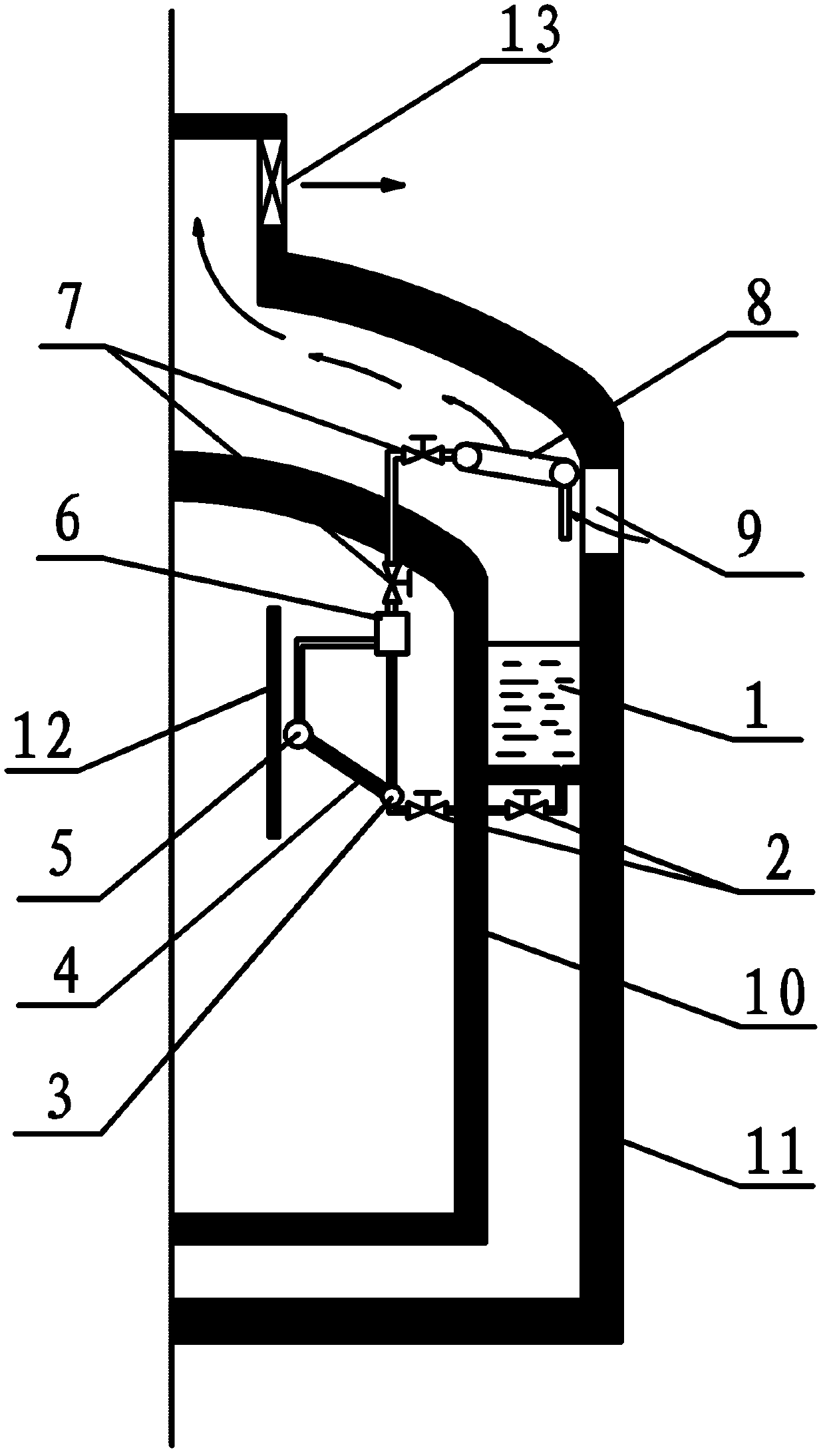
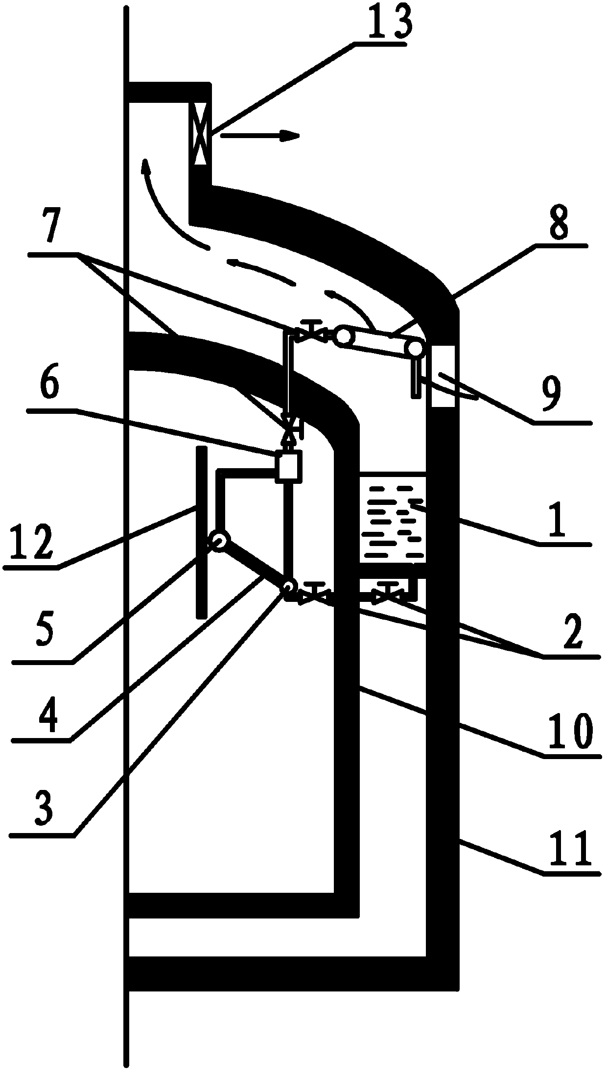
[0016] combine figure 1 , the system mainly includes an annular pool 1, isolation valves 2, 7, an internal evaporator tube bundle 4, a steam-water separator 6 and an external air cooler 8. Among them, the internal evaporator tube bundle 4 and the steam-water separator 6 are located in the upper space near the side wall of the inner concrete containment vessel 10; the annular pool 1 is located in the annular cavity between the inner concrete containment vessel 10 and the side wall of the outer concrete containment vessel 11 Inside; the external air cooler 8 is located between the domes of the inner concrete containment vessel 10 and the outer concrete containment vessel 11 near the outer sidewall. The lower part of the annular pool 1 is sequentially connected to the isolation valve 2, the lower head of the internal evaporator 3, the tube bundle of the internal eva...


PUM


Abstract

The invention aims at providing a passive safety shell cooling system comprising a water tank, an inner evaporator pipe bundle, a steam-water separator and an outer air cooler, wherein the water tank is positioned in an annular cavity formed by an inner-layer concrete safety shell and an outer-layer concrete safety shell; the outer air cooler is positioned between the dome of the inner-layer concrete safety shell and the dome of the outer-layer concrete safety shell; both an inner evaporator and the steam-water separator are positioned inside the inner-layer concrete safety shell; two ends of the inner evaporator are respectively connected with the steam-water separator through two pipes; the steam-water separator is connected with the outer air cooler through a first pipe extending out of the inner-layer concrete safety shell; and the inner evaporator pipe bundle is communicated with the water tank through a second pipe extending out of the inner-layer concrete safety shell. When accidents such as LOCA (Loss Of Coolant Accident) and MSLB (Main Steam Line Break) occur, the passive safety shell cooling system can be used for safely and reliably conducting heat out of the safety shell for a long term, ensuring the temperature inside the safety shell, and guaranteeing that pressure is no more than a limiting design value, thereby maintaining the integrity of the safety shell.

Description

technical field [0001] The invention relates to a cooling system, in particular to a cooling system in the fields of nuclear safety and thermal hydraulic technology. Background technique [0002] The containment is the last safety barrier to prevent the leakage of radioactive materials in the event of an accident in a nuclear power plant. In the event of severe accidents such as LOCA and MSLB, the containment cooling system must ensure that the temperature and pressure in the containment do not exceed the design allowable range, so as to maintain the integrity of the containment. [0003] At present, the double-layer containment design used in PWR nuclear power plants includes steel-concrete containment and concrete-concrete containment. The passive cooling systems proposed for the steel-concrete containment all use the steel containment as the accident isolation boundary and heat export interface, and its heat transfer performance is directly related to the safety of the e...

Claims


Application Information

Patent Timeline
IPC IPC(8): G21C15/18
CPCY02E30/30
Inventor 孙中宁范广铭阎昌琪丁铭王建军孙立成曹夏昕谷海峰
Owner HARBIN ENG UNIV
Learn More