Laser processing device and laser processing method

A laser processing method and laser processing technology, applied in positioning devices, laser welding equipment, metal processing equipment, etc., can solve the problems of processing position deviation, difficulty in precise processing, and wrinkles

Active Publication Date: 2012-08-15
PANASONIC CORP
View PDF11 Cites 4 Cited by
  • Summary
  • Abstract
  • Description
  • Claims
  • Application Information

AI Technical Summary

Problems solved by technology

As a result, the machining position of the workpiece is shifted or wrinkles are g

Method used


Image

  • Laser processing device and laser processing method
  • Laser processing device and laser processing method
  • Laser processing device and laser processing method

Examples


Embodiment approach 1

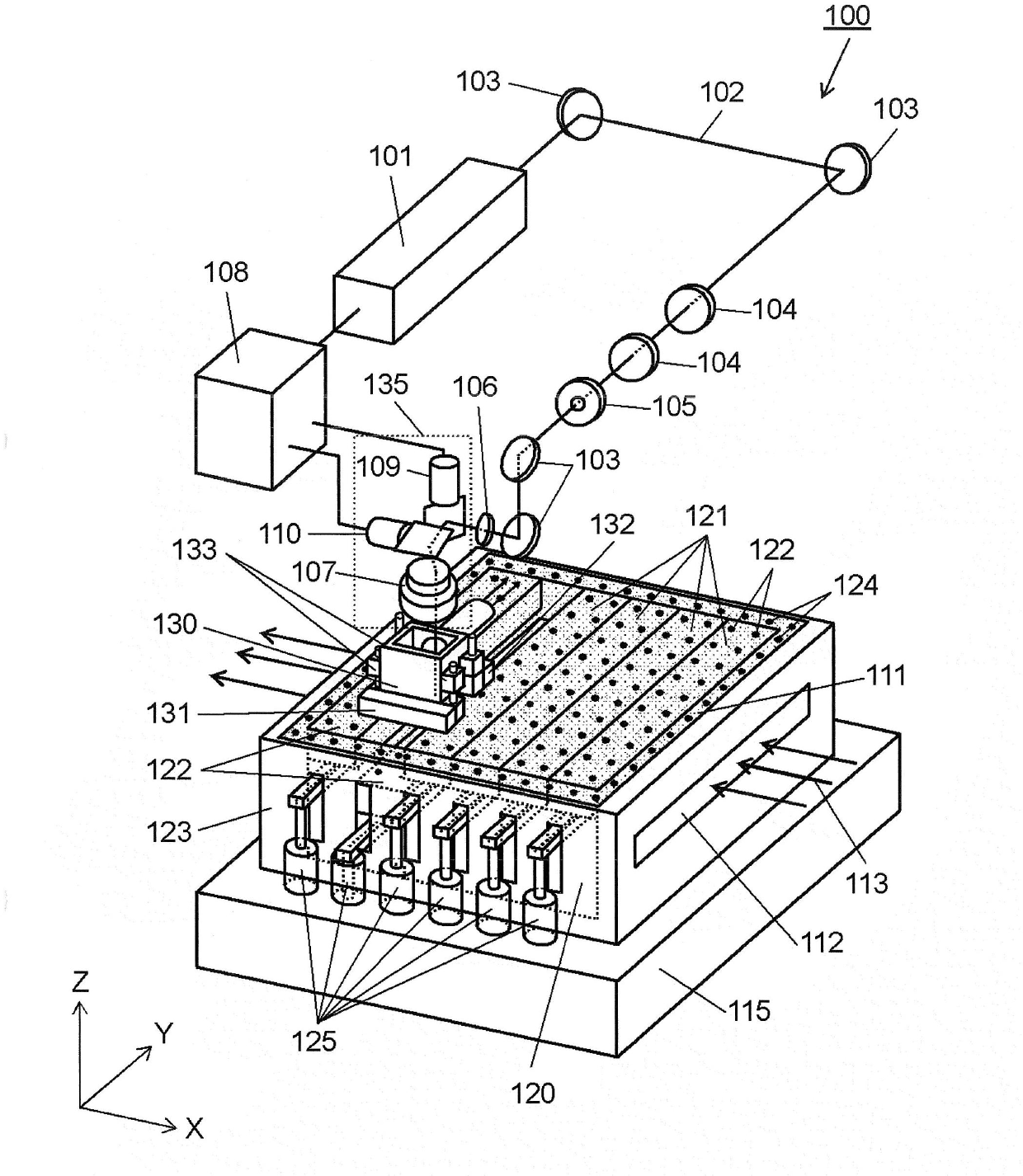
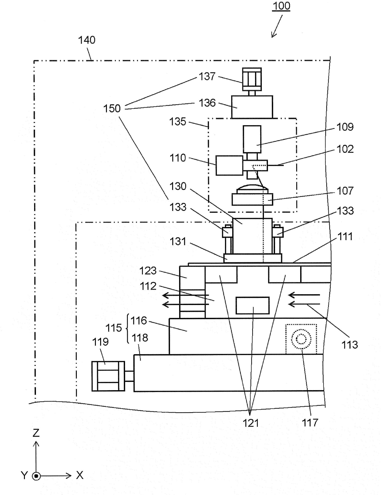
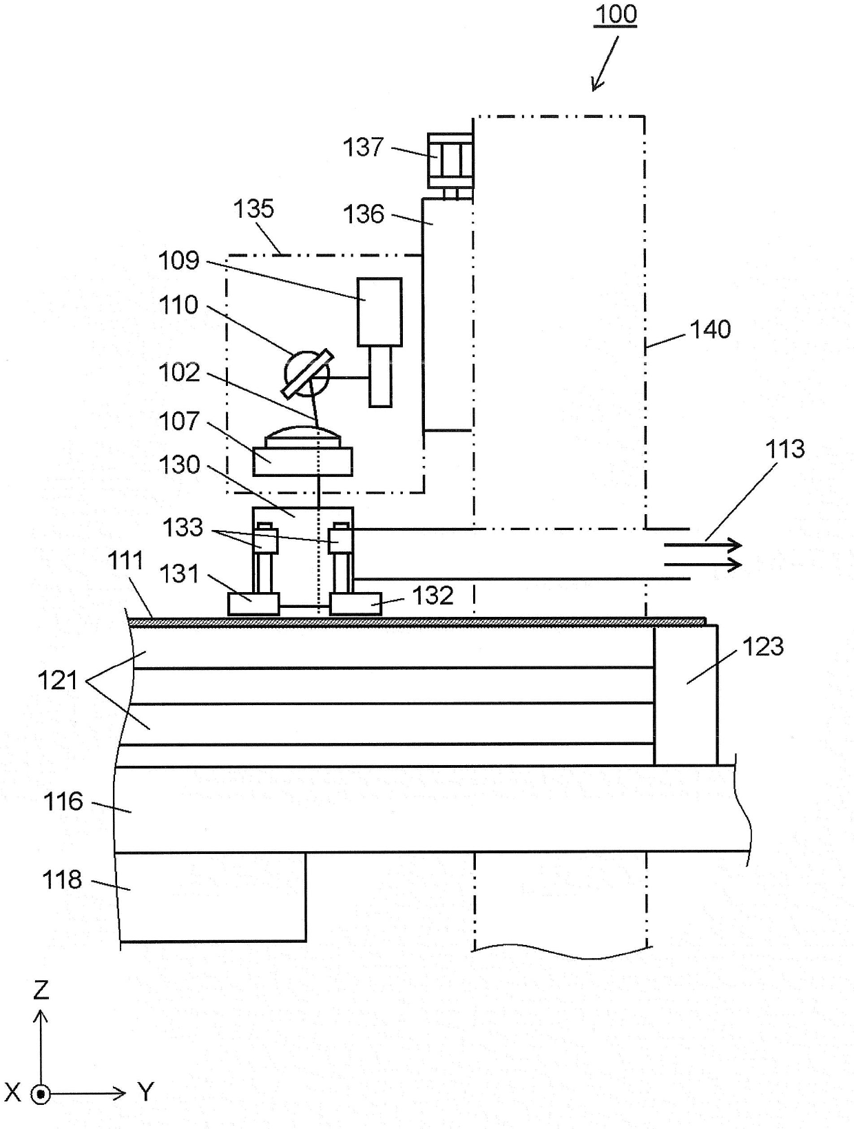
[0048] figure 1 It is a perspective view which shows the schematic structure of the laser processing apparatus 100 which concerns on an example of Embodiment 1 of this invention. figure 2 is a side view when viewing the laser processing device 100 from the Y direction, image 3 It is a side view seen from the X direction similarly.

[0049] Such as figure 1 As shown, a laser oscillator 101 internally oscillates laser light to emit laser light 102 . The emitted laser beam 102 changes its traveling direction by the mirror 103 . A collimator lens 104 for adjusting the beam diameter of the laser beam 102 is arranged in the advancing direction of the laser beam 102 whose advancing direction has been changed by the reflecting mirror 103 . A mask 105 for shaping the beam shape of the laser beam 102 passing through the collimator lens 104 and an aperture 106 for suppressing stray light of the laser beam 102 passing through the mask 105 are also disposed.

[0050] The laser lig...

Embodiment approach 2

[0110] Next, a different example of the processing method using the laser processing apparatus 100 of the present invention will be described. figure 1 , figure 2 and image 3 The structure of the laser processing apparatus 100 shown is the same as that of Embodiment 1 mentioned above. Similarly, a pair of upper surface adsorption devices 131 and 132 and an upper surface adsorption device elevating cylinder 133 for moving the upper surface adsorption devices 131 and 132 up and down are attached to the upper dust collecting device 130 . In Embodiment 2, an air cylinder is used as the upper surface adsorption device elevating cylinder 133, so that each of the upper surface adsorption devices 131, 132 can be independently moved up and down.

[0111] Figure 8A , Figure 8B , Figure 9A to Figure 9C It is a layout diagram showing an example of the setting of the processing area of ​​the workpiece 111 according to Embodiment 2 of the present invention. Figure 9A , Figure...


PUM


Abstract

This laser processing device (100) is provided with: a processing head section (135) which laser processes an item which is being processed; a mount section (120) which has a plurality of separated moveable mount sections (121) which rise and fall in the vertical direction, and which holds the item being processed; a processing table (115) which drives the mount section in the X and Y directions; an upper surface adhesion device (130) which is arranged above the item being processed and which adheres to the upper surface of the item being processed; and a drive unit (150) which drives the upper surface adhesion device so as to rise and fall in the vertical direction.

Description

technical field [0001] The present invention relates to a laser processing device for processing a workpiece by irradiating laser light, and more particularly to a laser processing device for processing a through hole (through hole processing). Background technique [0002] In recent years, with the miniaturization, high integration, and composite modularization of parts, the hole opening processing of the base material that is the basis for these requirements has also become smaller and smaller. In the existing processing methods, the more and more difficult. In order to meet these demands and respond to the reduction in diameter, drilling processing using lasers is increasing. Hole-drilling in a workpiece by laser light is roughly classified into two types: through-hole processing in which a through-hole is formed in a workpiece and blind-hole processing in which a non-through hole is formed in a workpiece. [0003] Figure 10 It is a side view which shows the structure ...

Claims


Application Information

Patent Timeline
IPC IPC(8): B23K26/10B23K26/08B23K26/38B23Q3/08B23Q3/15
CPCB23K26/0853B23K26/082
Inventor 小寺一知杉山勤西原学佐佐木义典樱井通雄
Owner PANASONIC CORP
Why Eureka
Try Eureka