Sand core structure for air flue of cylinder cover of engine

An engine cylinder and air passage sand core technology, which is applied to engine components, machines/engines, cylinder heads, etc., can solve the problems of poor positioning accuracy of the square core head, floating air passage core, easy bumping and friction, etc., and achieves high positioning accuracy. Effect

Inactive Publication Date: 2012-08-22
WUHU YONGYU AUTOCAR INDAL
View PDF7 Cites 15 Cited by
  • Summary
  • Abstract
  • Description
  • Claims
  • Application Information

AI Technical Summary

Problems solved by technology

However, this airway sand core structure has the following disadvantages: (1) the positioning accuracy of the square core head of the airway core is relatively poor; There is still a gap of 0.2-0.5mm between the matching core seats, which causes the airway core to float up under the action of the aluminum liquid during the pouring process.
What's more serious is that the height of the boss of the valve guide hole of the cylinder head has a large deviation, usually 0.5-1mm, and the height of the boss of the valve guide hole of the cylinder head directly affects the performance parameter of the intake air—the turbine ratio; (2) The square core head structure of the airway core has edges and corners. First, it is not easy to operate the core. Secondly, during the core setting process of this structure, it is easy to bump and rub and cause sand loss, which affects the quality of the casting after casting.

Method used


Image

  • Sand core structure for air flue of cylinder cover of engine
  • Sand core structure for air flue of cylinder cover of engine
  • Sand core structure for air flue of cylinder cover of engine

Examples


Embodiment 1

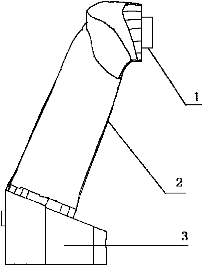
[0014] Such as figure 1 As shown, the present embodiment is an engine cylinder head airway sand core structure. The sand core includes a core body 2 and core heads at both ends of the core body 2. The core head at one end of the core body 2 is fixed in the core seat on the waterway core. The core head at the other end is fixed on the metal mold, and the core head fixed in the core head seat on the deep water channel core of the core body 2 is a cylindrical structure, and its axial direction is vertically inserted into the core head seat of the water channel core, such as figure 1 The cylindrical core head 1 on the upper part of the core body 2 shown, the core head fixed on the metal mold of the core body 2 is a stepped structure in cross section, as figure 1 The step-shaped core head 3 at the bottom of the core body 2 . The end face of the step-shaped core head 3 connected to the core body 2 is an inclined surface, and the step-shaped core head 3 is inserted longitudinally in...

Embodiment 2

[0016] On the basis of Embodiment 1, further, the cross-section of the core head fixed on the metal mold of the core body 2 is a three-stage stepped structure, and the height of the cross-section increases gradually, as figure 2 As shown, the stepped core head 3 has three steps, the structure is simple, the positioning is more precise, and the positioning accuracy of the core head is further improved. Of course, in addition to the three steps, there are other more alternatives.

Embodiment 3

[0018] On the basis of Embodiment 1 or Embodiment 2, the step-shaped core head 3 of the core body 2 is positioned through the fixing groove provided at the bottom of the metal mold, and the core head is embedded in the fixing groove of the metal mold longitudinally for fixing. The shape of the fixing groove is adapted to the shape of the stepped core head 3 . The fixing of the step-shaped core head 3 does not require side molds for positioning, but the fixing grooves at the bottom of the mold are used for positioning, which avoids the displacement of the airway core due to the matching of the molds during the mold closing process, and the positioning accuracy is high.


PUM


Abstract

The invention discloses a sand core structure for an air flue of a cylinder cover of an engine. A sand core comprises a core body and core heads at two ends of the core body; the core head at one end of the core body is fixed after being inserted into a core head base on a water channel core; the core head at the other end is fixed on a metal mould; the core head which is fixed in the core head base on the water channel core of the core body has a cylindrical structure; the core head is axially and vertically inserted into the core head base of the water channel core; and the core head of the core body fixed on the metal mould has a structure with a cross section of stair shape. By adopting the technical scheme, compared with the prior art, the sand core structure has the advantages that the cylindrical core head of the sand core of the air flue is fixed after being vertically inserted into the core head base on the water channel core; due to the cylindrical structure, the core-disassembling operation is easily performed; the positioning precision is high; no edged structure exists; the bumping and sand dropping are difficult to occur; when the stair-shaped core head at the other end of the sand core of the air flue is fixed, no side mould is required for positioning; the displacement of the sand core of the air flue caused by matching problem of the mould during the mould-combining process is avoided; and the positioning precision is higher.

Description

technical field [0001] The invention relates to casting equipment for an engine cylinder head, in particular to a sand core structure for an engine cylinder head airway. Background technique [0002] The intake and exhaust passage structures are an important part of the aluminum alloy cylinder head structure. One end is connected to the end face of the combustion chamber, and the other end protrudes from the side opening. Its dimensional accuracy and internal surface quality have an important impact on the overall performance of the cylinder head. . Because the airway structure is located inside the cylinder head, and its shape is mostly curved, its quality mostly depends on the casting process of this part. In the casting process of aluminum alloy cylinder heads, people often use resin airway sand cores with high strength and smooth surface to form the cylinder head airway structure. [0003] At present, in the airway sand core structure used in domestic aluminum alloy cy...

Claims


Application Information

Patent Timeline
Patent Type & Authority Applications(China)
IPC IPC(8): B22C9/10B22C9/24F02F1/14
Inventor 郑志勋
Owner WUHU YONGYU AUTOCAR INDAL
Why Eureka
Try Eureka