Angle steel welding fixture

A technology of welding fixture and angle steel, which is applied in the direction of welding equipment, auxiliary welding equipment, welding/cutting auxiliary equipment, etc., can solve the problems of short service life of the cage, gaps in the welding place, and weak welding, etc., so as to avoid desoldering, The effect of firm welding, improving welding efficiency and welding quality

Inactive Publication Date: 2012-08-22
SUZHOU TANGFENG ELECTRICAL APPLIANCE
View PDF0 Cites 12 Cited by
  • Summary
  • Abstract
  • Description
  • Claims
  • Application Information

AI Technical Summary

Problems solved by technology

However, for longer angle steel, it is easy to shift during welding, resulting in gaps in the weld and weak welding
After the machine is placed on the angle steel welded cage, the service life of the cage is very short due to vibration or vibration when the machine is running. After the angle steel is de-welded, it is very troublesome and time-consuming to re-weld

Method used


Image

  • Angle steel welding fixture
  • Angle steel welding fixture

Examples


Embodiment Construction

[0013] The present invention is described below in conjunction with accompanying drawing.

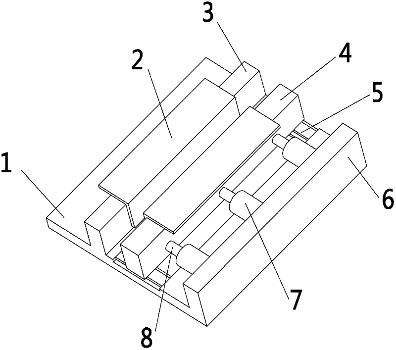
[0014] attached figure 1 It is an angle steel welding fixture according to the present invention, comprising a base 1, a fixed plate 4 and a cylinder 7; the base 1 is a rectangular plate, and a positioning plate 3 and a baffle plate 6 are fixed above the base 1; the positioning Plate 3 is located at the front end of base 1, and baffle plate 6 is located at the rear end of base 1; Said fixed plate 4 is located between positioning plate 3 and baffle plate 6, and fixed plate 4 can move back and forth on base 1; Said base 1 On the position where the fixed plate 4 moves, there is a slide rail 5; the fixed plate 4 slides on the slide rail 5; the cylinder 7 is fixed on the base 1, and is located between the fixed plate 4 and the baffle plate 6 There are three cylinders 7, which are respectively located at the left end, the right end and the middle of the fixed plate 4; the spacing of the thre...


PUM


Abstract

The invention discloses an angle steel welding fixture. The fixture comprises a base, a fixing plate and cylinders, wherein the base is an oblong plate; a positioning plate and a baffle are fixed above the base; the positioning plate is arranged at the front end of the base; the baffle is arranged at the rear end of the base; the fixing plate is arranged between the positioning plate and the baffle and can move back and forth on the base; the cylinders are fixed on the base and are arranged between the fixing plate and the baffle; the rear ends of the cylinder bodies are fixed on the baffle; and piston rods of the cylinders are fixedly connected with the fixing plate. When used for welding, the fixture has the following advantages: the angle steel is firmly welded, welding is convenient and fast to operate, the welding efficiency and quality are improved, the welded angle steel is prevented from sealing off due to machine vibration and the service life of the welded angle steel is ensured.

Description

technical field [0001] The invention relates to a clamp device, in particular to a clamp device for welding angle steel, and belongs to the technical field of welding auxiliary devices. Background technique [0002] Before installing some machinery and equipment, a cage is usually built with angle steel, which are all welded. Generally, when welding, the angle steel is placed on the ground first, and then welded after bonding. But for the longer angle steel, it is easy to shift during welding, resulting in gaps in the welding place and weak welding. After the machine is placed on the welded cage of the angle steel, the service life of the cage is very short due to vibration or vibration when the machine is running. After the angle steel is de-welded, it is very troublesome and time-consuming to re-weld. Contents of the invention [0003] In view of the above-mentioned technical problems, the object of the present invention is to provide a welding jig for angle steel whic...

Claims


Application Information

Patent Timeline
Patent Type & Authority Applications(China)
IPC IPC(8): B23K37/04
Inventor 唐祥根
Owner SUZHOU TANGFENG ELECTRICAL APPLIANCE
Why Eureka
Try Eureka