Machine hinge vertical compression clamping mechanism

A mold clamping and direct pressure technology, applied in the field of machine hinge direct pressure mold clamping mechanism, can solve the problems of complex hydraulic control, lubricating oil pollution, long cycle period, etc., to reduce lubricating oil pollution, reduce lubrication requirements, and improve product accuracy Improved effect

Active Publication Date: 2012-08-22
BORCH MACHINERY
View PDF7 Cites 5 Cited by
  • Summary
  • Abstract
  • Description
  • Claims
  • Application Information

AI Technical Summary

Problems solved by technology

[0002] The traditional hinged clamping mechanism obtains the clamping force by amplifying the force generated by the straightening of the hinge. It is difficult to control the magnitude of the clamping force, and it is also difficult to accurately set the clamping force as required. The power and demoulding force are generated by the amplification of the cylinder force. The larger the cylinder force required, the larger the diameter of the cylinder, and more power hydraulic oil is needed to participate in the rapid mold movement, resulting in high energy consumption; And the accumulation of processing tolerances of the templates makes the parallelism between the templates holding the molds not high, resulting in low machine precision. Due to the uneven force, the wear of the machine hinges is aggravated and there is no compensation device, which will further reduce the accuracy of the machine. Opening and closing the mold In order to overcome the moving frictional resistance of the movable template, especially the significant rotational frictional resistance generated by the steel sleeve in the hinge and the pin shaft under the load of the clamping force when the clamping force is generated, the steel sleeve in the hinge and the pin shaft have a A large amount of lubrication is required in the relatively rotating place, which will cause lubricating oil pollution to the machine. The uneven force of the clamping rod may cause the breakage of the clamping rod. The uneven force of the thread mold adjustment will easily lead to uneven mold adjustment or even thread burning. ;Traditional hydraulic direct press requires too much hydraulic oil to participate in the work, high energy consumption and low efficiency. If you want to improve efficiency, you need to improve the configuration, resulting in high cost; the traditional hydraulic two-platen machine has a long cycle and low efficiency due to many actions. The complex hydraulic control leads to insufficient machine stability; the deformation of the fixed platen of the traditional clamping mechanism cannot form self-compensation, which may easily lead to flashing of injection molded products

Method used


Image

  • Machine hinge vertical compression clamping mechanism
  • Machine hinge vertical compression clamping mechanism
  • Machine hinge vertical compression clamping mechanism

Examples


Embodiment Construction

[0030] The present invention will be further described in detail with an embodiment below, but it should be noted that the protection scope of the present invention is not limited thereto.

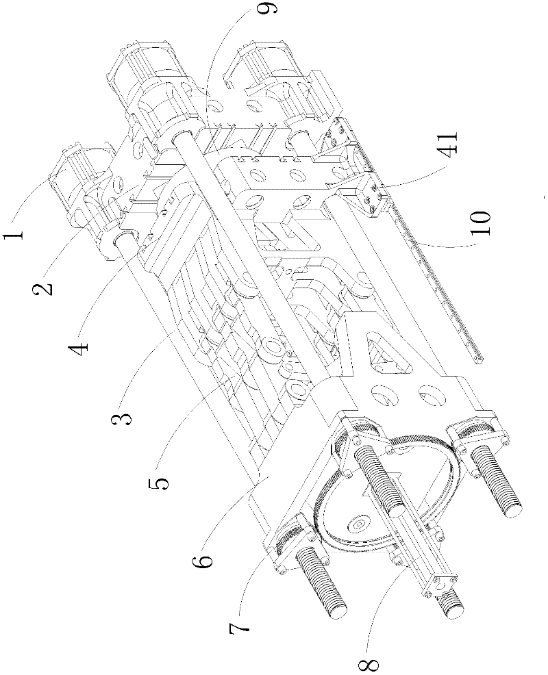
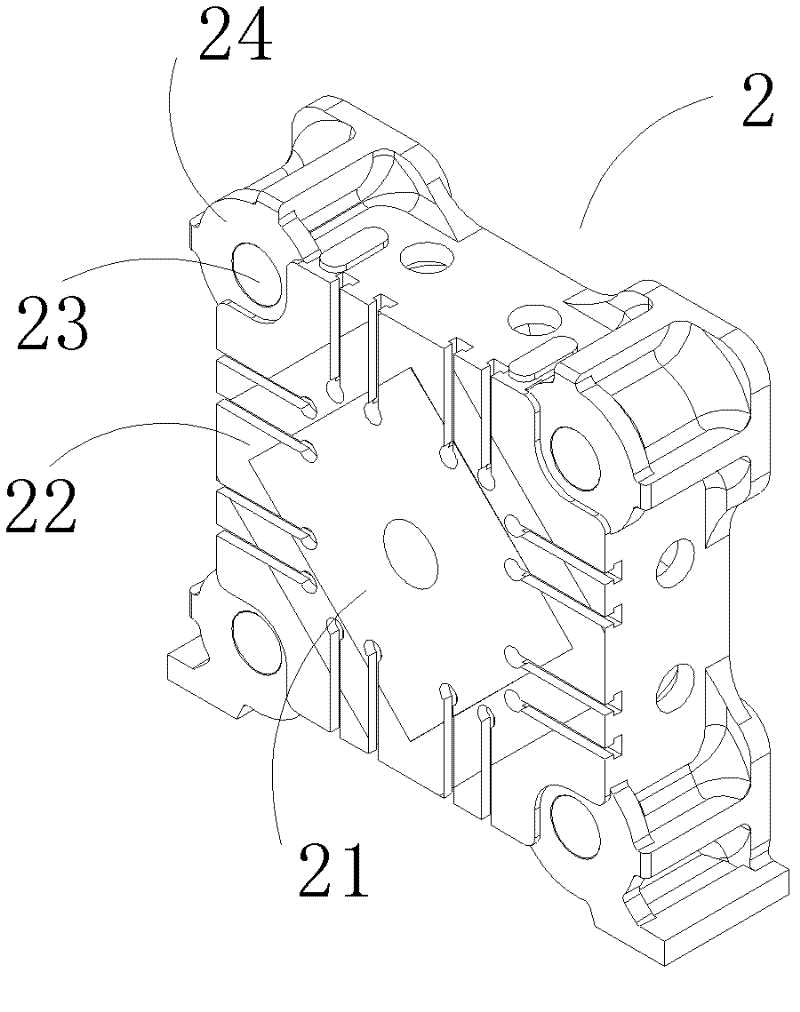
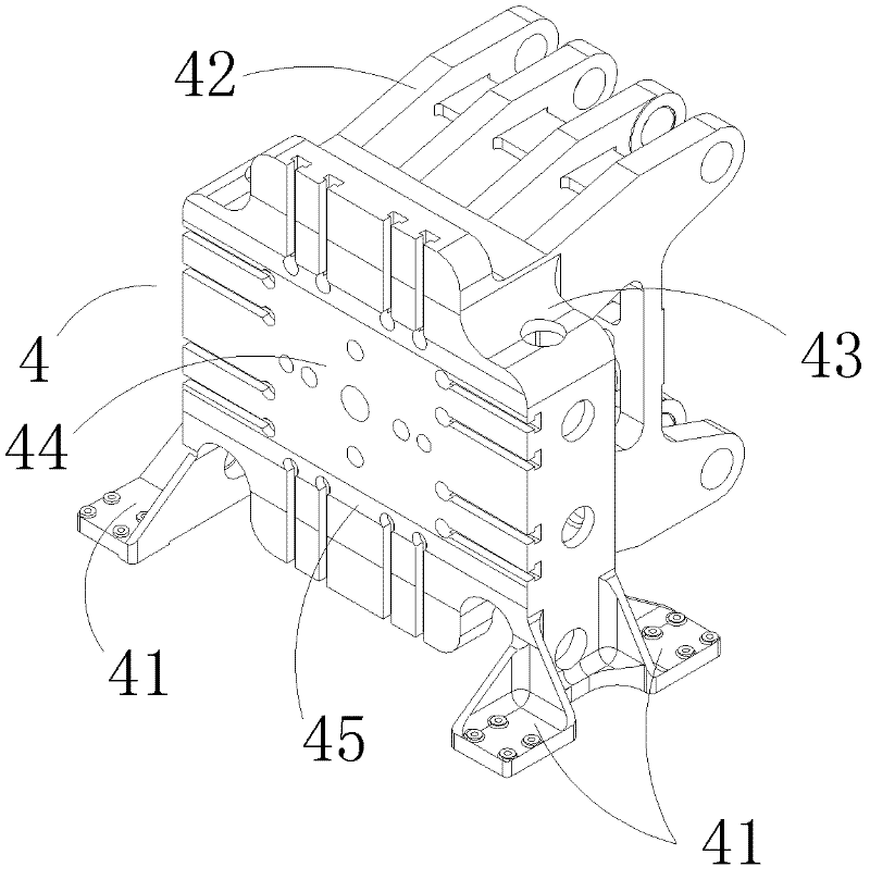
[0031] refer to Figure 1 to Figure 3 , a mechanical hinge direct pressure mold clamping mechanism, which includes a mold clamping cylinder assembly 1, a fixed platen 2, a mold clamping pull rod 3, a movable platen 4, a machine hinge assembly 5, a tail plate 6, a threaded mold adjustment assembly 7, and a mold shifting Execute component 8. The clamping cylinder assembly 1 is fixedly installed on the surface of the tie rod hole corner 24 outside the tie rod hole 23 of the fixed plate 2, and the threaded mold adjusting assembly 7 is installed in the tie rod hole (not shown in the figure) of the tail plate 6 ) on the outside angle plane; the movable template 4 is arranged between the tail plate 6 and the fixed template 2 and the movable template 4 is connected with the tail plate 6 through t...


PUM


Abstract

The invention discloses a machine hinge vertical compression clamping mechanism, which comprises a mould clamping cylinder assembly, a solid plate, a mould clamping pull rod, a movable mould plate, a machine hinge assembly, a tail plate, a thread mould adjustment assembly, and a mould shifting and driving execution assembly, wherein the mould clamping cylinder assembly is fixedly arranged on the outer side of the solid plate; the thread mould adjustment assembly is arranged on the outer side of the tail plate; the movable mould plate is arranged between the tail plate and the solid plate and is connected with the tail plate through the machine hinge assembly; one end of the mould clamping pull rod penetrates through the tail plate so as to form threaded connection with the thread mould adjustment assembly; the other end of the mould clamping pull rod penetrates through the solid plate so as to form movable fit connection with the mould clamping cylinder assembly in a manner of a mould clamping cylinder piston rod and form a mould clamping cylinder; the mould shifting execution assembly is arranged on the tail plate and form movable connection with the machine hinge assembly; and a code mould face of the solid plate is sequentially milled to be microsize from the center to the outer side so as to form a micro step face. According to the machine hinge vertical compression clamping mechanism, high speed and high efficiency can be realized, energy consumption is lower, mould adjustment is smoother, mould clamping precision is high, and production precision is greatly improved.

Description

technical field [0001] The present invention relates to the fields of injection molding machinery and die-casting molding machinery, and more specifically, relates to a machine-hinge straight-press mold-clamping mechanism for injection molding machinery and die-casting molding machinery. Background technique [0002] The traditional hinged clamping mechanism obtains the clamping force by amplifying the force generated by the straightening of the hinge. It is difficult to control the magnitude of the clamping force, and it is also difficult to accurately set the clamping force as required. The power and demoulding force are generated by the amplification of the cylinder force. The larger the cylinder force required, the larger the diameter of the cylinder, and more power hydraulic oil is needed to participate in the rapid mold movement, resulting in high energy consumption; And the accumulation of processing tolerances of the templates makes the parallelism between the templa...

Claims


Application Information

Patent Timeline
Patent Type & Authority Applications(China)
IPC IPC(8): B29C45/66B29C33/20
Inventor 饶启琛叶廷璧
Owner BORCH MACHINERY
Why Eureka
Try Eureka