Self-elevating rotating crane installation device for tall towers

An installation device and self-elevating technology, applied in cranes and other directions, can solve the problems of high hoisting cost, long construction period, and inability to meet fast-paced installation requirements.

Active Publication Date: 2012-08-22
YUNNAN CONSTR & INSTALLATION JOINT STOCK +1
View PDF6 Cites 1 Cited by
  • Summary
  • Abstract
  • Description
  • Claims
  • Application Information

AI Technical Summary

Problems solved by technology

Due to the characteristics of high towers, multiple geometric shapes, and variable cross-sections of large-scale towers, it is generally only possible to adopt on-site fabrication, hoisting, and installation in sections. long, it can no longer meet the fast-paced installation requirements, especially for towers over 100 meters; if large-scale hoisting mechanical equipment is...

Method used


Image

  • Self-elevating rotating crane installation device for tall towers
  • Self-elevating rotating crane installation device for tall towers
  • Self-elevating rotating crane installation device for tall towers

Examples


Embodiment 1

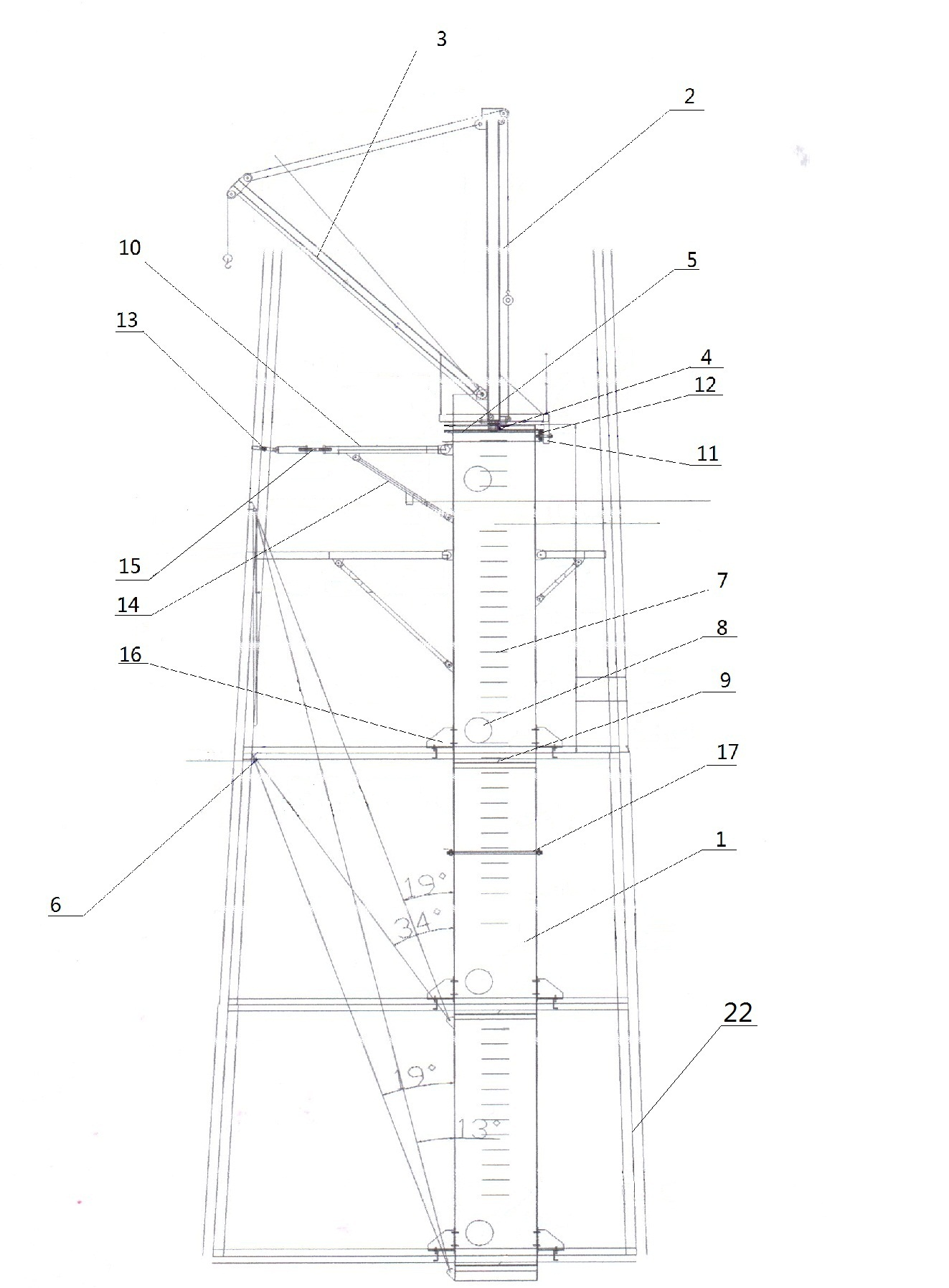
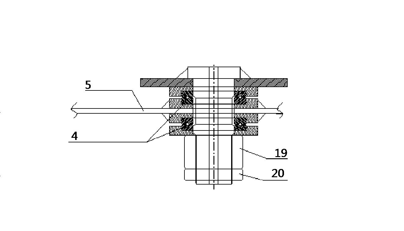
[0022] It is mainly composed of a central cylinder 1, a main mast 2, and an auxiliary mast 3. It is characterized in that the main mast 2 is located on the top of the central cylinder 1, and the connection between the main mast 2 and the central cylinder 1 is provided with a plane thrust ball bearing 4. The main mast 2 and the plane The thrust ball bearing 4 is fixed on the top plate 5 of the central cylinder 1 through nuts 19, the main mast 2 is connected with the auxiliary mast 3, the central cylinder 1 is connected with the tower beam 6, a ladder 7 is arranged on the central cylinder 1, and a ladder 7 is arranged on the central cylinder. 1 is provided with an operation hole 8 on the cylinder, and a platform 9 is provided inside the center cylinder 1. The disposal of the platform 9 is adapted to the operation hole 8, and an operation platform 10 is provided on the outer edge of the top of the center cylinder 1.

[0023] The connection between the main mast 2 and the top plate...

Embodiment 2

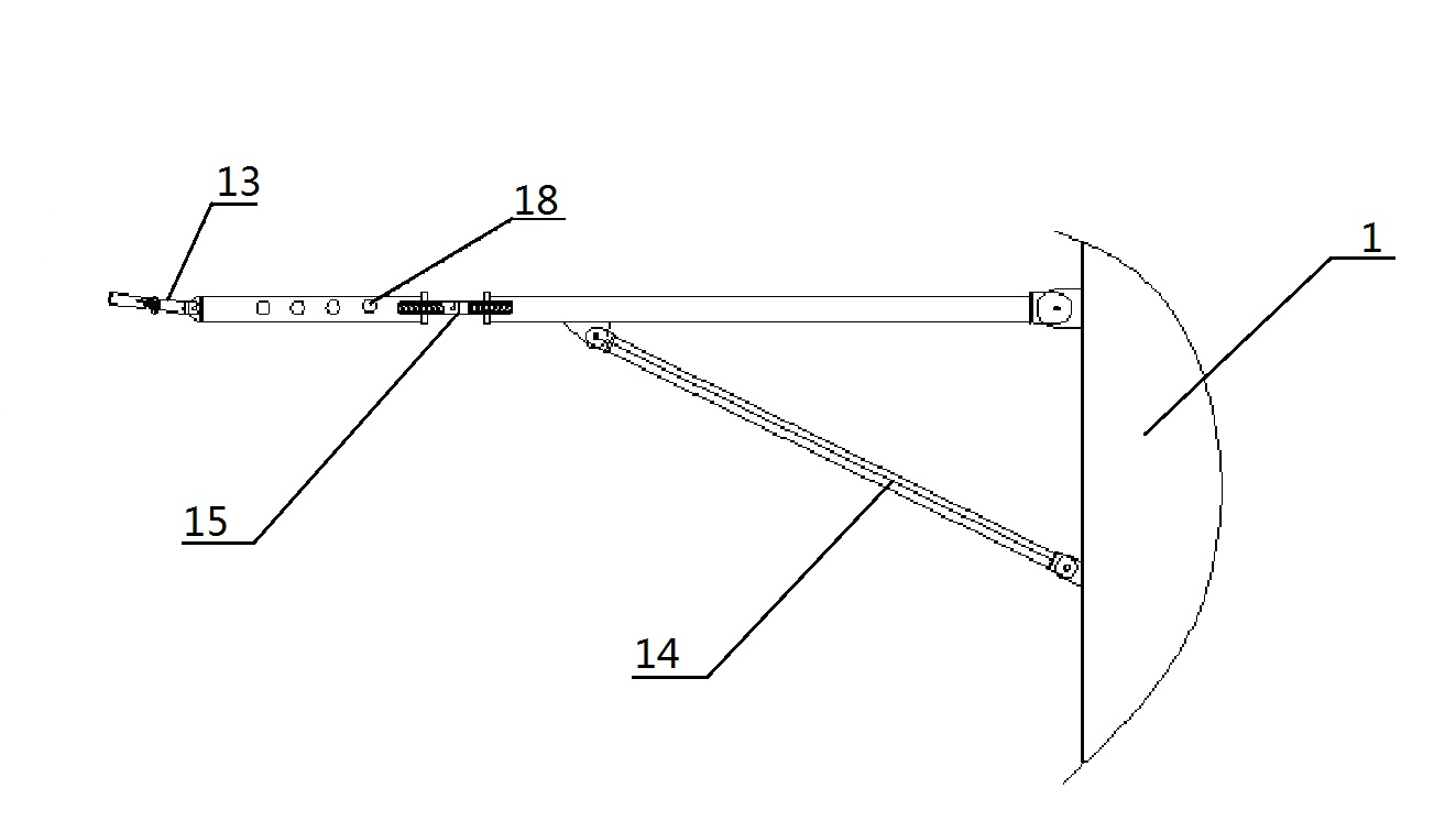
[0028] The present invention makes full use of the structural characteristics of the tower to make a φ1520mm×6mm steel coil pipe with a length of 17m as the center tube support. The center tube 1 is divided into two sections from the middle and connected by a flange 17 for the convenience of installation and removal. Use a crane to hoist the lower central tube 1 into the tower, center it with the adjusting screw 15, connect the central tube 1 with the tower beam 6 on the tower 22 with a corbel and fix it firmly, and then hoist the upper section into the tower and the lower section After connecting and fixing, the top platform and mast are installed; the 3-ton hoist is in place on the ground, fixed, and threaded with wire ropes; A Φ219×10 high 6m seamless steel pipe is erected on the top of the central tube 1 as the main mast 2, and a Φ159×10 long 6m seamless steel pipe is used as the auxiliary mast 3. Two pairs of planar thrust ball bearings 4 are installed at the bottom of th...


PUM


Abstract

Disclosed is a self-elevating rotating crane installation device for tall towers which relates to an installation device of tower cranes. The device mainly comprises a center cylinder, a primary mast and a secondary mast, wherein the primary mast is arranged on the top of the center cylinder, a plane thrust ball bearing is arranged at the connection portion of the primary mast and the center cylinder, the primary mast and the plane thrust ball bearing are fixed on a top plate of the center cylinder through a nut, the primary mast is connected with the secondary mast, the center cylinder is connected with a cross beam of a tower frame, a ladder stand is arranged on the center cylinder, an operation hole is arranged on a center cylinder body, a platform is arranged on the inner portion of the center cylinder, the arrangement of the platform is matched with the operation hole, and an operation platform is arranged on the periphery of the top of the center cylinder. The device is suitable for all tall tower structures which are required to be assembled and installed on site in new-built, technically-improved and renovation items in smelting and chemical industries. Particularly, the device can be used for installing tall towers without large cranes on narrow construction sites and can effectively improve quality and accuracy of on-site assembly and installation of towers.

Description

technical field [0001] The invention relates to a tower crane installation device, in particular to a self-elevating rotary tower crane device for installing a high tower. Background technique [0002] With the rapid development of various industries in recent years, new construction and renovation projects continue to develop in the direction of large-scale, and there are more and more towers for supporting devices; at the same time, with the desire of construction units to shorten the construction period, high Quality, safety, and fast-paced smooth installation of towers have become a new requirement for the installation industry that undertakes projects. Due to the characteristics of high towers, multiple geometric shapes, and variable cross-sections of large-scale towers, it is generally only possible to adopt on-site fabrication, hoisting, and installation in sections. long, can no longer meet the fast-paced installation requirements, especially for towers over 100...

Claims


Application Information

Patent Timeline
IPC IPC(8): B66C23/62
Inventor 不公告发明人
Owner YUNNAN CONSTR & INSTALLATION JOINT STOCK
Why Eureka
Try Eureka