Pay-off braking device for spindle of high-speed braiding machine

A high-speed knitting machine and braking device technology, which is applied to woven fabrics, textiles and papermaking, can solve the problems of large brake clearance, large brake transmission resistance, and unstable parking, and achieve accurate braking without clearance, high flexibility, and structure. simple effect

Inactive Publication Date: 2012-08-22
韩百峰
View PDF4 Cites 6 Cited by
  • Summary
  • Abstract
  • Description
  • Claims
  • Application Information

AI Technical Summary

Problems solved by technology

[0006] The purpose of the present invention is to provide a high-speed braiding machine spindle pay-off brake device to solve the problems of large brake clearance, unstable parking and large brake transmission resistance in the existing spindle brake device

Method used


Image

  • Pay-off braking device for spindle of high-speed braiding machine
  • Pay-off braking device for spindle of high-speed braiding machine
  • Pay-off braking device for spindle of high-speed braiding machine

Examples


Embodiment 1

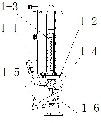
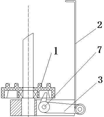
[0021] Embodiment 1: The brake device includes: bobbin seat 1, brake claw 3 and connecting rod 2; one end of brake claw 3 is pressed on the side wall of the inner circular groove under bobbin seat 1, and the other end of brake claw 3 is connected to Connecting rod 2.

[0022] The bobbin seat 1 is disc-shaped, with a hole in the middle of the disc, cylinders are evenly distributed on the circumference of the same center as the central hole, and a circular inner groove is arranged below the disc, and the inner wall of the circular inner groove is Raised tables are arranged.

[0023] The brake claw 3 is "L" shaped, with a pawl-shaped front end, connected to the circular inner groove under the bobbin seat 1, and can move in the circular inner groove, hooking the inner wall or disengaging the inner wall; the brake claw 3 is provided with a small hole at the bending point, and the small hole is sleeved on the fulcrum shaft 7, and the rear end is slidably connected with the connecti...


PUM


Abstract

The invention relates to a pay-off braking device for a spindle of a high-speed braiding machine and belongs to a spindle braking structure of a braiding machine. The pay-off braking device comprises a spool base, a braking claw and a connecting rod, wherein one end of the braking claw is pressed on a side wall of an inner circular groove under the spool base; the other end of the braking claw is connected with the connecting rod; the spool base has a shape of a disc; a hole is formed in the middle of the disc; cylinders are uniformly distributed on the circumference of the same circle center as the hole; the inner circular groove is arranged under the disc; raised platforms are arrayed on an inner wall of the inner circular groove; the braking claw is L-shaped; the front end of the braking claw is pawl-shaped and moves in the inner circular groove under the spool base; a small hole is formed at a bent part of the braking claw and is sleeved on a pivot shaft; and the rear end of the braking claw is in sliding connection with the connecting rod. The pay-off braking device has the advantages that: a pay-off line is controlled by the pay-off braking device in a point contact way; the spindle pay-off is easy and flexible; the abrasion is small; the braking is accurate and gapless; a transmission part is simple in structure, low in cost, high in flexibility and long in service life; a rough yarn and a spun yarn are compatible; the yarn is free from being broken; and the braiding is uniform.

Description

technical field [0001] The invention relates to a spindle brake structure of a braiding machine, in particular to a spindle pay-off brake device for a high-speed braiding machine. Background technique [0002] The high knitting machine spindle pay-off braking device that uses on the present braiding machine has top pin upward braking type and ratchet depressing type. [0003] exist figure 1 Among them, the structure of the lift pin upward braking type is: there is a faceplate (1-2) on the spindle body (1-1) of the lift pin upward brake type, and the faceplate (1-2) is sleeved on the bobbin shaft (1-2). 3) On the top, the bobbin shaft (1-3) is connected with the spindle body (1-1), and the spindle body (1-1) is provided with an ejector pin (1-4). The upper end of the ejector pin (1-4) is placed in the lower groove of the faceplate (1-2), and the ingot body (1-1) is covered with a wire pendant (1-5), and the wire pendant (1-5) and the ejector pin (1-4 ) in the horizontal ax...

Claims


Application Information

Patent Timeline
Patent Type & Authority Applications(China)
IPC IPC(8): D04C3/00
Inventor 韩百峰刘建峰
Owner 韩百峰
Why Eureka
Try Eureka