Weighted girder-less type strong-efficiency energy-saving oil pumping unit

A pumping unit and heavy hammer technology, which is applied in the field of high-efficiency and energy-saving oil pumping units, can solve the problems of high energy consumption and large structure, and achieve the effects of low energy consumption, the most energy consumption, and small impact force

Inactive Publication Date: 2012-08-22
刘昕
View PDF6 Cites 4 Cited by
  • Summary
  • Abstract
  • Description
  • Claims
  • Application Information

AI Technical Summary

Problems solved by technology

[0006] The purpose of the present invention is to overcome the disadvantages of the existing pumping unit, such as large structure and high energy consumption, and provide a heavy hammer beamless type high-efficiency energy-saving pumping unit with compact structure, high efficiency and energy saving

Method used


Image

  • Weighted girder-less type strong-efficiency energy-saving oil pumping unit
  • Weighted girder-less type strong-efficiency energy-saving oil pumping unit
  • Weighted girder-less type strong-efficiency energy-saving oil pumping unit

Examples


Embodiment

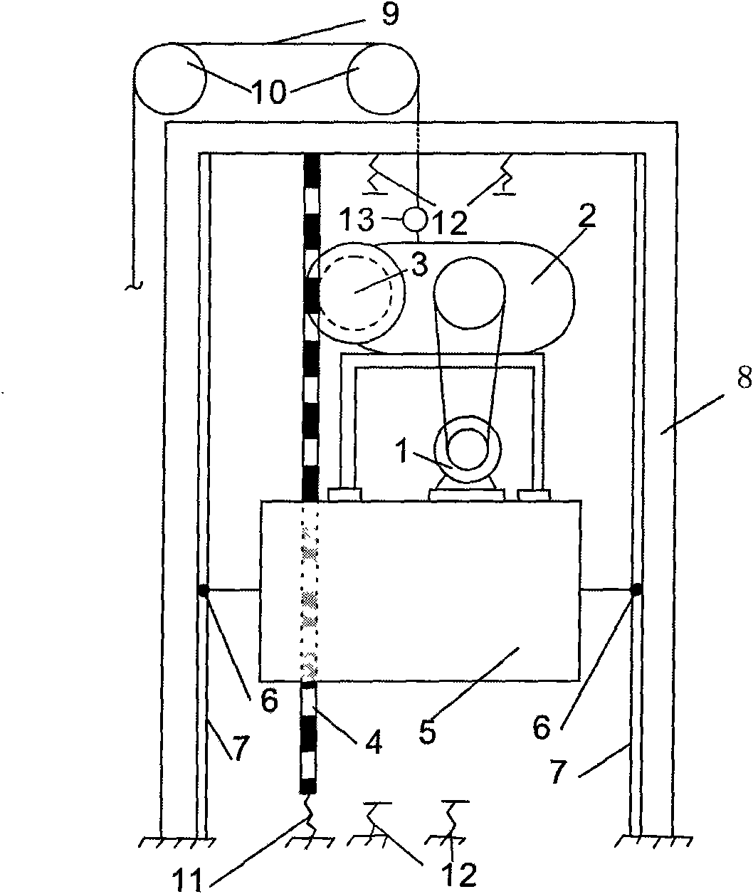
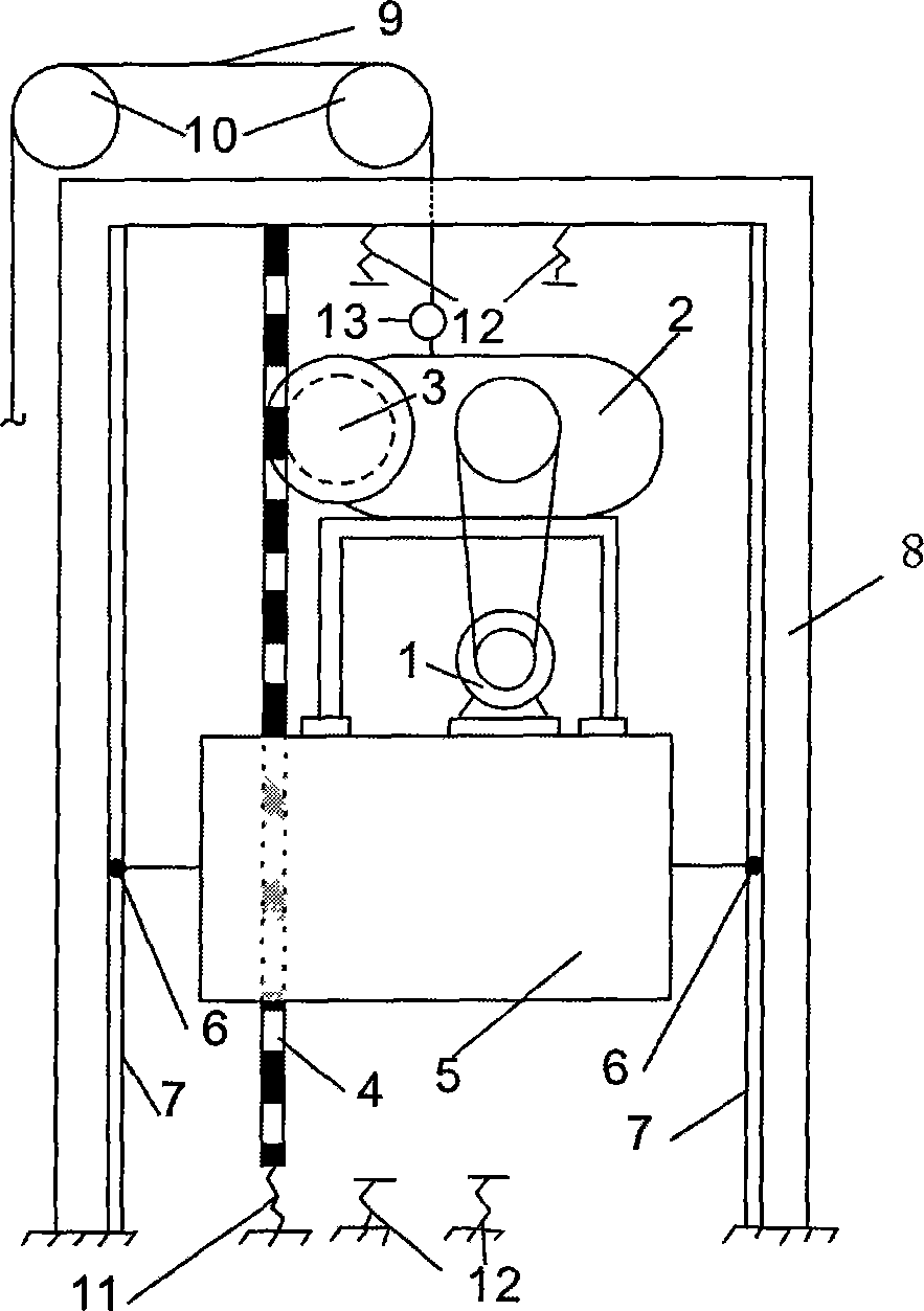
[0019] The lifting system of this embodiment uses a steel frame structure to connect the motor 1, the control box 2, and the weight 5 as a whole, and the rollers 6 are respectively connected on both sides of the weight 5 so that the whole can slide up and down in the guide rail 7.

[0020] The sprocket 3 and the motor 1 are connected by an intermittent mechanism. The chain 4 passes through the weight 5, the upper part is connected to the beam of the bracket 8, and the lower part is directly provided with a tensioner 11, which is fixedly connected to the ground foundation and connected to the sprocket 3. Engaged, the guide rail 7 and the bracket 8 are fixedly connected, the pulley 10 and the beam of the bracket 8 are connected to form a fixed system. The sensor 13 is used to display the force and operating conditions of the system. The lower end is fixedly connected to the cover of the control box 2, and the upper end is connected to the wire rope. 9 is fixedly connected, the other...


PUM


Abstract

The invention relates to oil production equipment, in particular to a high-efficiency energy-saving type oil pumping unit which is composed of a bracket 8, a motor 1, a control box 2, a sprocket wheel 3, a chain 4, a tensioner 11, a steel wire rope 9, a pulley 10, a heavy punch 5, buffers 12, a guide rail 7, idler wheels 6 and a sensor 13, wherein the motor, the control box and the heavy punch are connected into a whole by using a steel frame structure; the idler wheels are respectively connected at two sides of the heavy punch and can vertically slide on the guide rail, so that a lifting system is formed; an intermittent mechanism is arranged in the control box; the sprocket wheel is in transmission connection with the motor; the chain passes through the heavy punch; the upper part of the chain is fixedly connected with a transverse beam of the bracket; the tensioner is arranged at the lower part of the chain, fixedly connected with a ground foundation and meshed with the sprocket wheel; the guide rail is fixedly connected with an upright post of the bracket; the pulley is fixedly connected with the transverse beam of the bracket; the lower end of the sensor is fixedly connected to the box cover of the control box; the upper end of the sensor is fixedly connected with the steel wire rope; the other end of the steel wire rope is connected with an underground sucker rod through the pulley; the plurality of buffers are respectively installed at the upper part and the lower part; the upper part is fixed on the transverse beam of the bracket; and the lower part is fixed on the ground foundation.

Description

Technical field [0001] The invention relates to a petroleum extraction equipment, in particular to a high-efficiency and energy-saving petroleum pumping unit. Background technique [0002] The traditional beam pumping unit has been used in the world for more than one hundred years. At present, the pumping unit is still widely used in countries all over the world. The large and high-energy pumping equipment is indeed very much in line with the current high-tech era. Inconsistent. Although there are some beamless pumping units in the world, most of them are to change the forward and reverse rotation of the motor to achieve the reciprocating movement of the sucker rod, which causes frequent starting of the motor, resulting in a number of motor starting currents. When multiple pumping units operate at the same time, the grid voltage drop is too large, and this beamless pumping unit is still operating with high energy consumption. [0003] Chinese Patent Application No. 200810073860.2 ...

Claims


Application Information

Patent Timeline
Patent Type & Authority Applications(China)
IPC IPC(8): E21B43/00
Inventor 刘定现
Owner 刘昕
Why Eureka
Try Eureka