Method for converting digital signal to synchro/rotary transformer signal

A resolver and self-aligning machine technology, applied in the direction of instruments, electric/magnetic devices to transmit sensing components, measuring devices, etc., can solve the problems of popularization and application in the field of unfavorable angle measurement and control, single output type and frequency, and poor adaptability and other issues, to achieve the effect of wide operating frequency, multiple output types, and strong adaptability

Active Publication Date: 2012-08-29
连云港杰瑞电子有限公司
View PDF3 Cites 14 Cited by
  • Summary
  • Abstract
  • Description
  • Claims
  • Application Information

AI Technical Summary

Problems solved by technology

The existing digital-axis-angle converter can only realize the conversion of one signal type, one signal frequency and one signal voltage, with low precision, single output type and frequency, and poor adaptability, which is not conducive to the promotion of angle measurement and control fields application

Method used


Image

  • Method for converting digital signal to synchro/rotary transformer signal
  • Method for converting digital signal to synchro/rotary transformer signal
  • Method for converting digital signal to synchro/rotary transformer signal

Examples


Embodiment 1

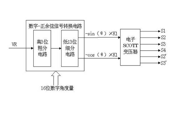
[0019] Embodiment 1, with reference to Figure 1-5 , a method for converting digital signals to auto-synchronizers / resolvers. The circuit for realizing the method includes a digital-sincosine signal conversion circuit and an electronic SCOTT transformer. The digital-sincosine signal conversion circuit can be subdivided into high 3-bit coarse points The circuit and the lower 13-bit subdivision circuit receive 16-bit natural binary digital angle and a reference signal with a frequency of DC ~ 1kHz, and generate a high-precision 6.81V sine-cosine signal to the electronic SCOTT transformer. The electronic SCOTT transformer passes through different jumper methods. Realize line-line voltage 11.8V auto-tuner signal, line-line voltage 11.8V resolver signal or line-ground voltage 6.81V sine-cosine signal output. The conversion method achieves the highest conversion accuracy of ±1 arc minute, the signal frequency range is DC to 1kHz, and the output signal type is programmable from synch...

Embodiment 2

[0020] Embodiment 2, in the digital signal described in embodiment 1 to the autosynchronizer / resolver conversion method: the described digital-sincosine signal conversion circuit divides the 16-bit digital quantity θ into α and β two Part, α is the upper 3-digit rough fraction angle: 0°, 45°, 90°, 135°, 180°, 225°, 270°, 315°, one of the 8 values, that is, the circumference is divided into 8 etc. β is the subdivision digital angle of the lower 13 digits: 0°~(45°-1LSB), that is, the fan in the range of 0~45° is divided into 211=8192 equal parts, 1LSB=0.055°; digital-sincosine signal conversion circuit Therefore, it can be subdivided into the upper 3-bit rough division circuit and the lower 13-bit subdivision circuit to realize various items related to α and β, and finally obtain the sine-cosine signal in the range of full-angle "α+β".

Embodiment 3

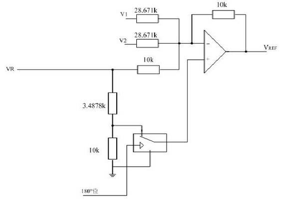
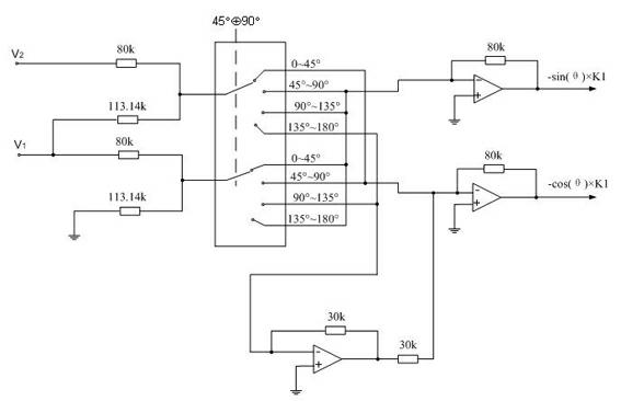
[0021] Embodiment 3, in the digital signal described in embodiment 1 or 2 to the synchro / resolver conversion method: in the high 3-bit coarse division circuit of the digital-sincosine signal conversion circuit, the 180 ° control bit is passed through the analog switch and precision resistors to realize the inversion of the reference signal, so as to realize the output of sine and cosine signals to Switching; K is the effective value of the signal line-ground voltage; the 45° control bit realizes the mutual switching between sinβ and sin (45°-β) through an analog switch; the 45° and 90° control bits generate sinα through an analog switch and a precision resistor network, The function values ​​of cosα, sin(α+45°) and cos(α+45°) can be used to realize the sine-cosine function value of four quadrants with a total of 8 rough points.


PUM


Abstract

The invention provides a method for converting a digital signal to a synchro/rotary transformer signal. A circuit for realizing the method comprises a digital/sine-cosine signal converting circuit and an electronic SCOTT transformer. The digital/sine-cosine signal converting circuit receives 16-bit natural binary digital angle measurement and a reference signal with a frequency of DC-1 kHz, generates a high-precision 6.81-V sine-cosine signal, and sends the high-precision 6.81-V sine-cosine signal to the electronic SCOTT transformer; a line-line voltage 11.8-V synchro signal, a line-line voltage 11.8-V rotary transformer signal or a line-ground voltage 6.18-V sine-cosine signal is output by the electronic SCOTT transformer in different jumper manners; a conversion precision is +/-1 arc minute, and a signal frequency is DC-1 kHz; and a type of the output signal is a synchro/rotary transformer/sine-cosine signal programmable type. The method provided by the invention has the advantages of reasonable design, high precision, more output types, wide working frequency, strong adaptability and the like.

Description

technical field [0001] The invention belongs to the technical field of signal simulation and testing, in particular to a conversion method from a digital signal to an synchro / resolver signal. Background technique [0002] The common shaft angle signals include synchro signals / resolver signals and sine-cosine signals. The digital-axis-angle converter converts the digital angle signals sent by the computer into three-wire synchro signals / four-wire resolver signals and two-wire The sine-cosine signal is the core device in the modern axis-angle electronic conversion technology, and is widely used in the fields of aerospace, aviation, radar, fire control and industrial automation. The existing digital-axis-angle converter can only realize the conversion of one signal type, one signal frequency and one signal voltage, with low precision, single output type and frequency, and poor adaptability, which is not conducive to the promotion of angle measurement and control fields applica...

Claims


Application Information

Patent Timeline
Patent Type & Authority Applications(China)
IPC IPC(8): G01D5/14G01B7/30
Inventor 奚志林夏伟张焱萍朱明锋
Owner 连云港杰瑞电子有限公司
Why Eureka
Try Eureka