

Lens driving device, auto-focusing camera, and mobile terminal device with camera
A lens driving device and lens technology, which can be used in cameras, focusing devices, electromechanical devices, etc., and can solve problems such as inability to achieve
- Summary
- Abstract
- Description
- Claims
- Application Information
AI Technical Summary
Problems solved by technology
Method used
Image

Examples
Embodiment Construction
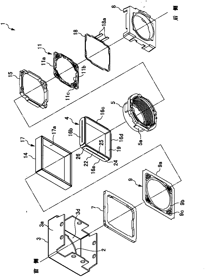
[0043] Embodiments of the present invention will be described below with reference to the attached documents. First, refer to the attached drawing Figure 1 to Figure 5 , the first embodiment of the present invention will be described in detail. A lens driving device 1 related to this embodiment is a lens driving device for an autofocus camera incorporated in a mobile phone.
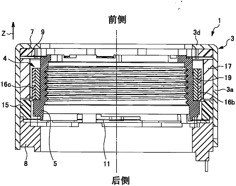
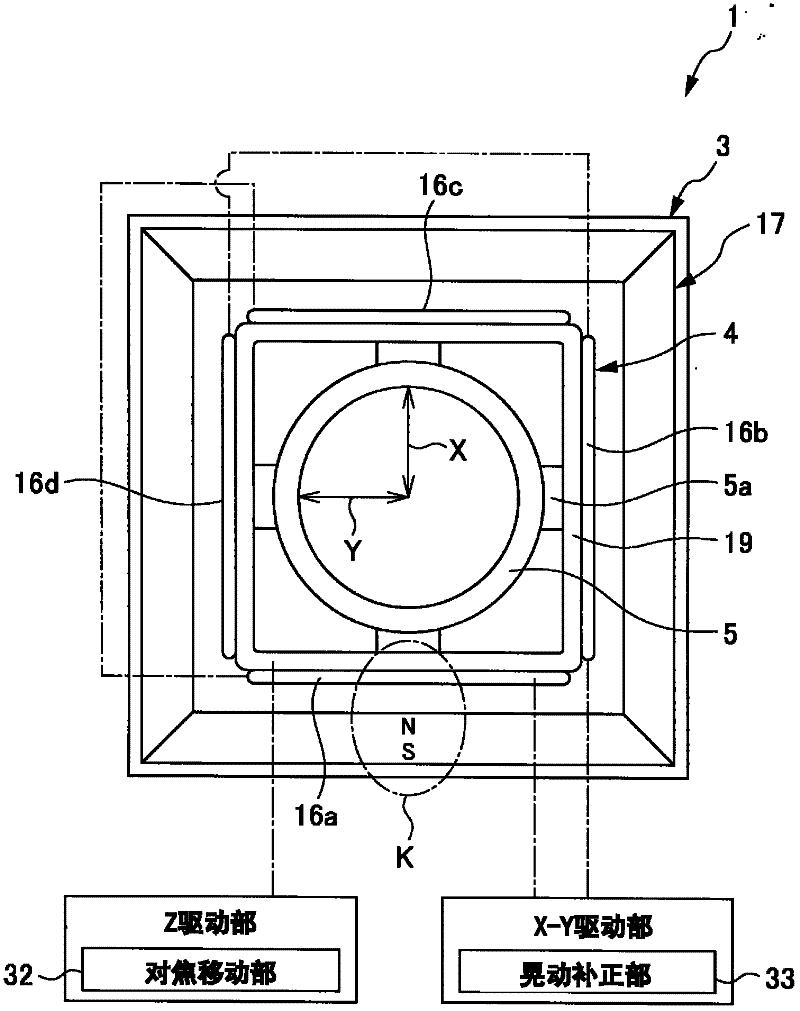
[0044] In this lens driving device 1, such as figure 1 As shown, the lens support body 5 supporting the lens (not shown) on the inner circumference, the yoke 3 as a part of the fixed body freely supporting the lens support body 5 on the inner circumference side, and the yoke 3 inside the yoke 3 On the circumference, stack the front spacer (insulator) 7, the front spring 9, the first magnet 17, the rear spacer 15 (insulator), the rear spring 11, and the terminal member 18 in sequence, and fix the base 8 . Such as figure 1 and figure 2 As shown, the coil body 4 is fixed to the outer periphery of the...
PUM
 Abstract
Description
Claims
Application Information