Stable cold field emission electron source

An electron source, field emission technology, applied in the field of electron sources

Active Publication Date: 2012-08-29
FEI CO
View PDF10 Cites 7 Cited by
  • Summary
  • Abstract
  • Description
  • Claims
  • Application Information

AI Technical Summary

Problems solved by technology

However, these improved CFE sources still exhibit noise in the emission current after short periods of source operation

Method used


Image

  • Stable cold field emission electron source
  • Stable cold field emission electron source
  • Stable cold field emission electron source

Examples


no. 1 example

[0042] Figure 7is a schematic diagram of a portion of a cold field emitter electron source showing a first embodiment 700 of the emitter tip region. The emitter wire 702 has a sharpened end 703 that emits electrons 710 under the influence of a high electric field at the tip 703 caused by a high voltage applied between the emitter tip 703 and the extractor 708 . A volume enclosing tip 703 is formed between the emitter enclosing electrode (EEE) 752 and the inner surface of the extractor 708 . Cleaning filament 730 is shown between EEE 752 and extractor 708 . An important consideration in the design of the source region of this first embodiment is the aspect ratio between the EEE 752 and the outer radius of the extractor 708 and the gap separating the EEE 752 from the inner surface of the extractor 708 . A larger aspect ratio prevents more backscattered electrons generated from the inner surface of the extractor 708 from hitting other (possibly unclean) surfaces in the gun, su...

no. 3 example

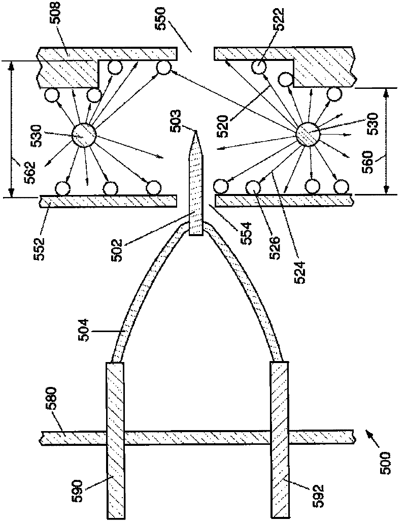
[0046] Figure 9 is a schematic diagram of a portion of the cold field emitter electron source of the present invention showing a third embodiment 900 of the emitter tip region. The emitter wire 902 has a sharpened end 903 that emits electrons 910 under the influence of a high electric field at the tip 903 caused by a high voltage applied between the emitter tip 903 and the extractor 908 . Cleaning filament 930 is shown between EEE 952 and extractor 908 . A volume enclosing tip 903 is formed between the emitter enclosing electrode (EEE) 952 and the inner surface of the extractor 908 . For this embodiment, EEE 952 has an outer shield ring 990 that prevents the escape of backscattered electrons 971 emitted from region 904 on extractor 908 and backscattered electrons 972 reflected from EEE 952, as the picture shows. The benefit of the improved BSE seal in this third embodiment has to be balanced against a slightly reduced pump speed from the source tip region. An additional b...


PUM


Abstract

A cold field emission (CFE) electron source for a focused electron beam system such as a transmission electron microscope (TEM), scanning transmission electron microscope (STEM), or scanning electron microscope (SEM) is disclosed. The source employs an emitter enclosure electrode behind the CFE tip which, in conjunction with the extractor electrode, defines a closed volume that can be thoroughly cleaned by electron impact desorption (EID) and radiative heating from a heated filament located between the emitter enclosure electrode and extractor electrode. The extractor electrode can be provided with a countersink which restrains backscatter electrons generated by an extractor from arriving parts of arriving sources and guns not cleaned by EID. Precleaning of an emitter enclosing electrodes before cold field-emission and extractor electrodes substantially improves both source emission stability and frequency noise characteristics, thereby realizing source operation with enough time interval for the application of TEM, STEM and SEM.

Description

technical field [0001] The present invention relates generally to electron sources, and more particularly to cold field emission electron sources for use in focused electron beam systems. Background technique [0002] In focused electron beam systems, a column is typically used to focus the electron beam onto the surface of the target to be imaged and (optionally) processed with the beam. In these columns, an electron source generates an initial beam of electrons that is passed into an electron "gun" that typically focuses charged particles into a roughly parallel beam that enters the body of the column. Various types of electron sources have been used in focused electron beam systems, including thermionic cathodes, Schottky emitters, and cold field emitters (CFE). Among them, CFE is characterized by the highest brightness and the smallest energy spread, thereby potentially achieving the smallest beam size at the target at the highest current density, thus enabling improved...

Claims


Application Information

Patent Timeline
Patent Type & Authority Applications(China)
IPC IPC(8): H01J1/304H01J37/073
CPCH01J37/063H01J37/073H01J2237/022H01J23/06
Inventor K·刘G·A·施温
Owner FEI CO
Why Eureka
Try Eureka