Control device for induction heating device and method for controlling induction heating system and induction heating device

An induction heating device and control device technology, applied in induction heating control, induction heating device, induction heating, etc., can solve problems such as uneven temperature distribution of conductor plates, achieve simple and reliable induction heating control, and prevent temperature distribution from becoming uneven effect

Active Publication Date: 2012-08-29
NIPPON STEEL CORP
View PDF7 Cites 15 Cited by
  • Summary
  • Abstract
  • Description
  • Claims
  • Application Information

AI Technical Summary

Problems solved by technology

If the frequency of the electric power supplied to the heating coil becomes higher in this way, the temperature near the ends (edges) of the conductor plate in the plate width direction will be higher than the temperature near the center portion of the conductor plate in the plate width direction, and the temperature in the plate width direction of the conductor plate will be higher. The temperature distribution may become uneven
[0012] As described above, in the prior art, there is a problem that when the conductor plate is heated using the induction heating device of the transverse system, if the plate passing speed of the conductor plate changes, the temperature distribution in the plate width direction of the conductor plate becomes uneven.

Method used


Image

  • Control device for induction heating device and method for controlling induction heating system and induction heating device
  • Control device for induction heating device and method for controlling induction heating system and induction heating device
  • Control device for induction heating device and method for controlling induction heating system and induction heating device

Examples


no. 1 Embodiment approach )

[0052] First, a first embodiment of the present invention will be described.

[0053]

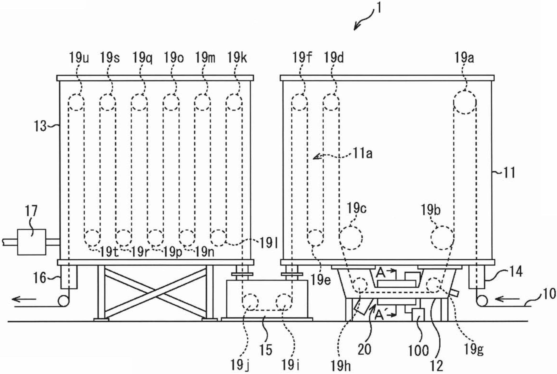
[0054] figure 1 It is a side view showing an example of a schematic configuration of a continuous annealing line for steel sheets.

[0055] exist figure 1 Among them, the continuous annealing line 1 includes a first container 11, a second container 12, a third container 13, a first seal roll assembly 14, a transfer device 15, a second seal roll assembly 16, a gas supply device 17, and rolls 19a- 19u, the induction heating device 20 and the control device 100 of the induction heating device. In addition, an induction heating system is constituted by the induction heating device 20 and the control device 100 of the induction heating device.

[0056] The first seal roll assembly 14 conveys the strip-shaped steel plate 10 into the first container 11 while isolating the first container 11 from the outside air. The strip-shaped steel plate 10 conveyed into the first container 11 by the firs...

no. 2 Embodiment approach )

[0140] Next, a second embodiment of the present invention will be described. In the aforementioned first embodiment, the alternating current I L Directly from the MERS 130 to the induction heating device 20 . In contrast, in this embodiment, the alternating current I L Flows from the MERS 130 to the induction heating device 20 via the transformer. Thus, in the configuration of the present embodiment, a transformer is added to the configuration of the first embodiment described above. Therefore, in the description of this embodiment, regarding the same parts as those of the first embodiment described above, Figure 1 ~ Figure 6B The attached symbols are the same symbols and detailed explanations are omitted.

[0141] Figure 7 It is a figure which shows an example of the structure of the control apparatus 200 of an induction heating apparatus.

[0142] Such as Figure 7 As shown, the control device 200 of this embodiment, in Figure 4 In the control device 100 of the fi...

no. 3 Embodiment approach )

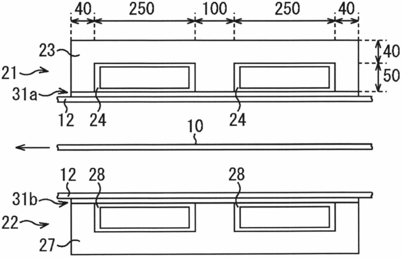
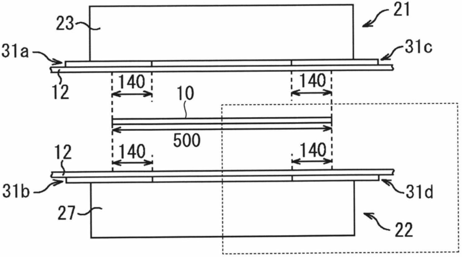
[0147] Next, a third embodiment of the present invention will be described. In the aforementioned first and second embodiments, flat plates are used as the shielding plates 31 a to 31 d provided in the induction heating device 20 . On the other hand, in this embodiment, a recess is provided on the shielding plate provided on the induction heating device 20 . In this manner, the present embodiment differs from the first and second embodiments described above in part of the configuration of the shielding plate. Therefore, in the description of this embodiment, regarding the same parts as those of the above-mentioned first and second embodiments, the following description will be added. Figure 1 to Figure 7 The attached symbols are the same symbols and detailed explanations are omitted.

[0148] Figures 8A-8C It is a figure which shows an example of the structure of an induction heating apparatus. Figure 8A , Figure 8B , Figure 8C corresponding to Figure 2A , Figur...


PUM


Abstract

A transverse type induction heating device crosses an alternating magnetic field with a plate surface of a conductive plate being threaded, thereby inductively heating the conductive plate. A control device for this induction heating device controls AC power output to a heating coil of the induction heating device and comprises: a magnetic energy regeneration bidirectional current switch for outputting AC power to the heating coil; a frequency setting device for setting an output frequency based on at least one of the relative permeability, resistivity, and plate thickness of the conductive plate; and a gate control device for controlling the switching operation of the magnetic energy regeneration bidirectional current switch on the basis of the output frequency set in the frequency setting device.

Description

technical field [0001] The invention relates to a control device of an induction heating device, an induction heating system and a control method of the induction heating device. It is especially suitable for inductively heating a conductor plate by making an alternating magnetic field cross the conductor plate substantially perpendicularly. [0002] This application is based on and claims priority to Patent Application No. 2009-283255 filed in Japan on December 14, 2009, and uses the content thereof here. Background technique [0003] Conventionally, for example, an induction heating device has been used when heating a conductor plate such as a steel plate that is passed through in a manufacturing line. The induction heating device is a device that has a heating coil and heats a conductor plate by an eddy current induced by the heating coil. In this induction heating device, an eddy current is induced in a conductor plate by an alternating magnetic field (alternating curr...

Claims


Application Information

Patent Timeline
Patent Type & Authority Applications(China)
IPC IPC(8): H05B6/10C21D1/42H05B6/06
CPCC21D1/04C21D1/42C21D9/56C21D9/60C21D11/00H05B6/06H05B6/104H05B6/362Y02P10/25H05B6/10H05B6/04
Inventor 福谷和彦真弓康弘武智俊也梅津健司
Owner NIPPON STEEL CORP
Why Eureka
Try Eureka