
Power Transmission Devices and Work Vehicles

A technology for power transmission devices and vehicles, which is applied to power devices, transmission parts, lifting devices, etc., can solve problems such as large accommodation space, and achieve the effect of reducing space and reducing the space in the axial direction of the wheel.

Active Publication Date: 2014-10-22
SUMITOMO HEAVY IND LTD
View PDF7 Cites 0 Cited by
  • Summary
  • Abstract
  • Description
  • Claims
  • Application Information

AI Technical Summary

Problems solved by technology

Therefore, including the aforementioned Patent Documents 1 and 2, the power transmission device for driving the wheels of the forklift is actually arranged on the axially outer side of the wheels, and as a result, a large accommodation space is required.

Method used


Image

  • Power Transmission Devices and Work Vehicles
  • Power Transmission Devices and Work Vehicles

Examples


Embodiment Construction

[0021] Hereinafter, an example of an embodiment of the present invention will be described in detail with reference to the drawings.

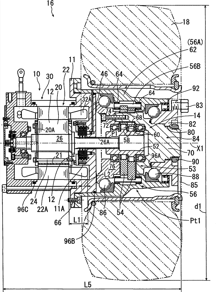
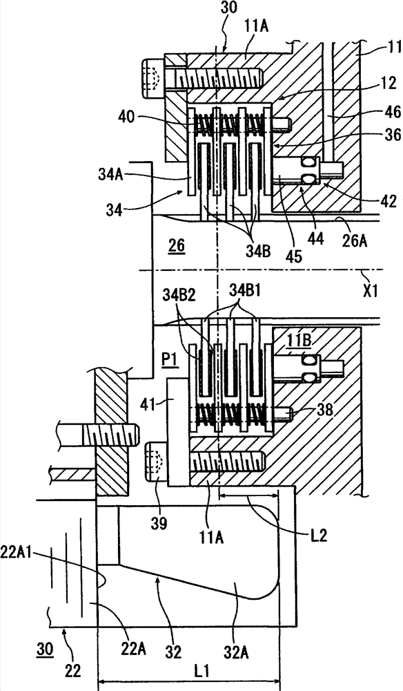
[0022] figure 1 It is a cross-sectional view showing a structure in which a power transmission device according to an example of an embodiment of the present invention is applied to drive a wheel of a forklift, figure 2 It is an enlarged cross-sectional view of the main part near the braking mechanism.

[0023] This power transmission device Pt1 is equipped with an IPM motor 10, a brake mechanism 12, and a speed reducer 14, and is used to independently drive each front wheel (wheel: figure 1 Only one side is shown) 18.

[0024] The IPM motor 10 has a rotor 20 and a stator 22 for extracting a rotational output. A plurality of plates (plates) 20A are stacked on the rotor 20 , and permanent magnets 21 are embedded in the rotor 20 . The IPM motor 10 with permanent magnets 21 embedded in the rotor 20 is more efficient than an SPM motor (a motor...


PUM


Abstract

A power transmission device that drives a wheel of a working vehicle includes a motor having a rotor for extracting rotation output, and a stator around which a coil for forming a magnetic field is wound; and a brake mechanism that brakes the rotation of a shaft that rotates integrally with the rotor. The brake mechanism includes a multiplate type braking part composed of a plurality of friction plates, and some of the friction plates may be stored radially inside a coil end of the coil.

Description

technical field [0001] This application claims priority based on Japanese Patent Application No. 2011-044407 filed on March 1, 2011. The entire content of the application is incorporated in this specification by reference. [0002] The present invention relates to a working vehicle and a power transmission device for driving wheels of the working vehicle. Background technique [0003] For example, Patent Document 1 discloses a power transmission device that drives wheels of a forklift (work vehicle). The forklift disclosed in Patent Document 1 includes a motor, a speed reducer for decelerating the rotation of the motor, and a brake mechanism for braking the rotation of the wheels as a power transmission device for driving the wheels. The reducer consists of a three-stage parallel shaft reduction mechanism. The brake mechanism is provided in a structure in which a rotor of the motor is extended toward the opposite-load side of the motor, and a disc brake device is assemble...

Claims


Application Information

Patent Timeline
Patent Type & Authority Patents(China)
IPC IPC(8): B60K17/12F16D55/24
CPCH02K7/1021B60K2007/0092F16D2121/04B60K17/046B66F9/07509F16D55/36B60K7/0007B60L2220/44Y02T10/64B60K17/04B60T1/06F16H57/10
Inventor 山本章
Owner SUMITOMO HEAVY IND LTD
Learn More