Online industrial robot calibration device based on spatial curved surface restraint

An industrial robot and curved surface constraint technology, which is applied in the direction of measuring devices, optical devices, instruments, etc., can solve the problems of robot end position deviation, large error, and low positioning accuracy of industrial robots, so as to achieve easy development, expand calibration space, reduce The effect of small errors

Active Publication Date: 2014-07-02
NANJING UNIV OF SCI & TECH
View PDF4 Cites 0 Cited by
  • Summary
  • Abstract
  • Description
  • Claims
  • Application Information

AI Technical Summary

Problems solved by technology

Small changes in the zero position of the robot cause a large deviation in the position of the end of the robot due to the magnification of the rod length, etc.
It is generally believed that 90% of the problems that lead to low positioning accuracy of industrial robots come from the zero position of robots (W.S.Newman and D.W.Osborn, "A new method for kinematic parameter calibration via laser line," in Proc.IEEE Int.Conf.Robot. Autom., 1993, vol.2, pp.160–165)
Yong Liu and Ning Xi proposed a calibration method based on single-point constraints (Yong Liu, Ning Xi, and Jianguo Zhao, "Development and Sensitivity Analysis of a Portable Calibration System for Joint Offset of Industrial Robot," IEEE / RSJ International Conference on intelligent Robots and Systems on louis, 11-15October2009), Liu Yong proposed a zero calibration method for industrial robots in the invention patent of an industrial robot zero self-calibration method and device (patent number: 201010267775.7), This method uses a laser to emit a laser beam, and the PSD (position sensitive device) receives the laser beam. Since the PSD is fixed, a large error will occur when the cylindrical laser beam is obliquely projected onto the center point of the PSD.

Method used


Image

  • Online industrial robot calibration device based on spatial curved surface restraint
  • Online industrial robot calibration device based on spatial curved surface restraint
  • Online industrial robot calibration device based on spatial curved surface restraint

Examples


Embodiment Construction

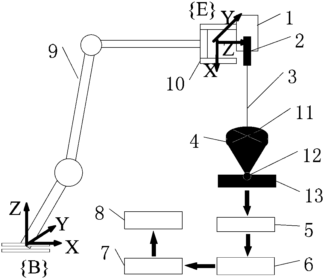
[0019] to combine figure 1, the online calibration device for industrial robots based on spatial surface constraints in the present invention includes a receiving device for a point source laser 2 and a laser beam 3, and the receiving device is composed of a position sensitive device (PSD for short) 4, a ball joint 12, a base 13, and a signal processing circuit 5. Data acquisition card 6, industrial control computer 7, and industrial robot controller 8. The laser 2 is rigidly fixed to the end 10 of the robot through the connecting device 1. During the calibration process, the relationship between the laser 2 and the end remains unchanged. The receiving device is placed In the working space of the industrial robot body 9, the PSD4 is fixedly connected to the ball joint 12 through a rigid connecting rod, the data collector card 6 is connected to the PSD4 through the signal processing circuit 5, and the data collector card 6 can be connected to the industrial control computer thro...


PUM


Abstract

The invention discloses an online industrial robot calibration device and an online industrial robot calibration method based on a spatial curved surface restraint, wherein the online industrial robot calibration device comprises a point light source laser and a receiving device for a laser beam; the receiving device is composed of a PSD (phase-sensitive detector), a ball joint, a base, a signal processing circuit, a data acquisition card, an industrial control computer, and an industrial robot controller; the laser is rigidly fixed at the tail end of a robot via a connecting device; the receiving device is placed in a working space of an industrial robot body; the PSD is fixedly connected with the ball joint via a rigid connecting rod; the data acquisition card is connected with the PSD via the signal processing circuit; and the data acquisition card is connected with the industrial control computer. The laser beam of the online industrial robot calibration device disclosed by the invention can be vertically projected onto a central point of the PSD, thus further reducing the error generated by that the cylindrical laser beam is slantwise projected on the central point of the PSD.

Description

a technical field [0001] The invention belongs to the calibration technology of industrial robots, in particular to a self-calibration method and device for the joint zero position of an industrial robot. Two background technology [0002] With the expansion of the application range of industrial robots and the need for complex tasks, the positioning accuracy of industrial robots is becoming more and more important. At present, industrial robots have high repeatability (0.1mm or higher), but (absolute) positioning accuracy is very low (up to 1cm or worse). The problem of positioning accuracy has seriously restricted the application capabilities and scope of industrial robots. Although there are many factors that lead to the low positioning accuracy of the robot, such as gear error, thermal expansion, and mechanical deformation of the robot rod, the most important factor comes from the parameter error of the robot kinematics model. Robot calibration technology is the most ef...

Claims


Application Information

Patent Timeline
Patent Type & Authority Patents(China)
IPC IPC(8): G01B11/00
Inventor 刘永
Owner NANJING UNIV OF SCI & TECH
Why Eureka
Try Eureka