
Non-contact electrocardiogram sensor and application of non-contact electrocardiogram sensor

A non-contact, electrical sensor technology, applied in the field of biomedical signal measurement, which can solve problems such as inability to accurately diagnose heart disease, local skin irritation, patient discomfort, etc., to achieve reduced impact, simple use, great flexibility and comfort. Effect

Inactive Publication Date: 2012-09-12
SOUTHEAST UNIV
View PDF8 Cites 37 Cited by
  • Summary
  • Abstract
  • Description
  • Claims
  • Application Information

AI Technical Summary

Problems solved by technology

However, as the incidence of heart disease continues to increase, and clinical segmental ECG detection cannot accurately diagnose some special heart disease (such as arrhythmia, myocardial ischemia), such diseases are random, sudden, Intermittent, making long-term, portable, daily ECG monitoring aroused widespread concern
[0004] At present, the development of the ECG Holter instrument meets the above needs, but because it still uses the traditional contact electrode to measure the body surface potential, the long-term contact between the electrode and the skin will bring great irritation to the local skin, and even cause skin allergies and fester, which is bound to bring a lot of discomfort to the patient

Method used

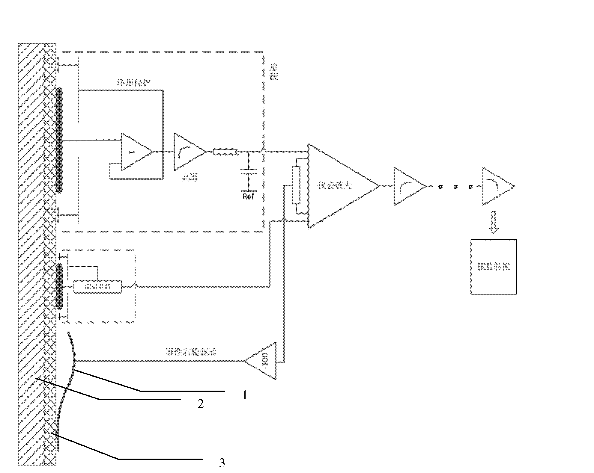
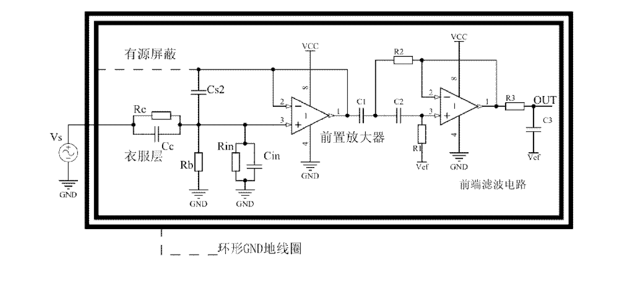
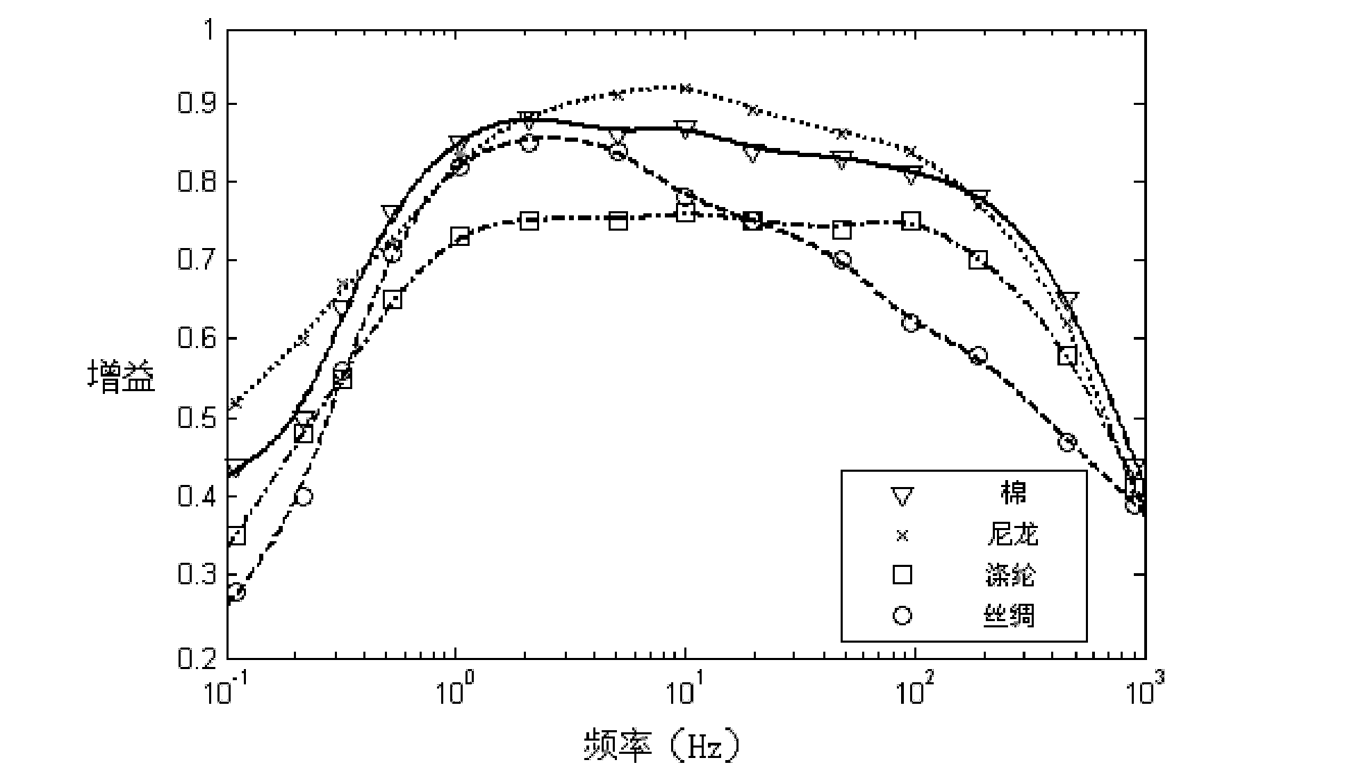

Image

  • Non-contact electrocardiogram sensor and application of non-contact electrocardiogram sensor
  • Non-contact electrocardiogram sensor and application of non-contact electrocardiogram sensor
  • Non-contact electrocardiogram sensor and application of non-contact electrocardiogram sensor

Examples


Embodiment Construction

[0029] Such as Figure 4 As shown, the non-contact ECG sensor includes a circular double-sided PCB board 13 with a diameter of 3.9 cm and a semi-closed steel-aluminum alloy shielding box 4 (Figure A). Figures B and C are respectively the two surfaces of the electrode 13 of the PCB board of the non-contact ECG sensor. The central part of the B drawing surface adopts a circular exposed induction sheet 9 with a diameter of 2.5 cm, and the surface is plated with a layer of tin. There are two annular shielding rings with a width of 0.35cm around the induction sheet 9, the inner side is the shielding ring 8, and its surface is covered with a layer of insulating silk screen film. The outer side is the ground wire shielding ring 7, and the surface is also plated with a layer of tin. The shielding ring 8, the ground wire shielding ring 7, and the induction sheet 9 are insulated from each other and are on the same plane. The central circular area 12 of drawing C is a copper-clad area...


PUM


Abstract

The invention relates to a non-contact electrocardiogram sensor, which adopts a round double-side printed circuit board (PCB) electrode, wherein three regions are arranged on one side, the three regions are in an electric insulation state, the center round region is a sensing sheet, an annular shielding region and an annular ground wire region are in sequential arrangement towards the outside, three regions are also arranged on the other side, the center round region is a copper covering region, a patch welding region comprising a prepositive operation amplifier and a front end filter is arranged in the center of the copper covering region, the outer periphery of the copper covering region is the annular ground wire region, the region simultaneously occupied by the sensing sheet and the adjacent annular shielding region is symmetrical to the copper covering region arranged on the other side, the annular ground wire regions arranged on the two sides are symmetrical, the output end of the prepositive operation amplifier is respectively connected with the annular shielding region and the copper covering region, the ground end of the prepositive operation amplifier is respectively connected with the annular ground wire regions arranged on the two sides, and the input of the prepositive operation amplifier is connected with the output of the sensing sheet. The double-side PCB electrode is positioned at the open opening end of a metal shielding box, the side provided with the sensing side faces the open opening, and the side provided with the copper covering region faces an inner cavity of the shielding box.

Description

technical field [0001] The invention relates to the monitoring of electrocardiographic signals, in particular to a non-contact electrocardiographic sensor and its application, belonging to the field of biomedical signal measurement. Background technique [0002] Bioelectricity is important information that reflects various physiological states of the human body. The detection and recording of various bioelectricity of the human body has become a reliable basis for mastering the functions of human organs, clinical diagnosis and treatment, and daily health monitoring. Heart disease is one of the major diseases that threaten human health, and electrocardiogram is an important means to detect heart disease. [0003] In traditional ECG measurement systems, Ag / AgCl disposable electrode sheets with conductive glue or suction cup and clip-on electrodes are usually used. These electrodes are in direct contact with the surface skin of the human body. However, as the incidence of hear...

Claims


Application Information

Patent Timeline
Patent Type & Authority Applications(China)
IPC IPC(8): A61B5/0402A61B5/0408
Inventor 周平刘梦星鲁豫杰吕菲汪丰
Owner SOUTHEAST UNIV
Learn More