Cooling water circulating and recycling system for normalizing furnace

A technology of cooling water circulation and normalizing furnaces, which is applied to furnaces, heat treatment furnaces, furnace types, etc., can solve the problems of high operating costs, large amounts of cooling water, large particle size of sewage impurities, etc., to achieve simple installation and operation, prolong equipment life, The effect of improving work efficiency

Inactive Publication Date: 2014-08-13
WISDRI WUHAN WIS IND FURNACE
View PDF5 Cites 0 Cited by
  • Summary
  • Abstract
  • Description
  • Claims
  • Application Information

AI Technical Summary

Problems solved by technology

The disadvantages of the direct discharge method: a large amount of cooling water needs to be introduced, the operating cost is high, and the discharged sewage impurities have a large particle size, which makes it difficult to meet the sewage discharge requirements stipulated by the state and enterprises
The circulation method saves a lot of water, but the current system has shortcomings: there are a lot of impurities in the cooling water, including a large number of iron oxide scales of different sizes produced during the heat treatment and cooling of steel plates and strips, and iron oxides produced in the system circulation , sludge, inorganic salts and other sundries, etc., these impurities will gradually make the nozzle nozzle of the aerosol and water spray device smaller, change the spray speed of the nozzle, reduce the spray momentum and cooling effect, until it is completely blocked
Especially for nozzles that work discontinuously, they are more likely to be clogged, and if they are exposed to high temperatures in the absence of water, they will deform and seriously affect the cooling effect of the workpiece.
At the same time, the effective adjustment range of this nozzle is very small, and the nozzle must be replaced to increase the adjustment range, thus affecting the stable operation of the entire system

Method used


Image

  • Cooling water circulating and recycling system for normalizing furnace
  • Cooling water circulating and recycling system for normalizing furnace
  • Cooling water circulating and recycling system for normalizing furnace

Examples


Embodiment Construction

[0030] The present invention will be further described below in conjunction with accompanying drawing.

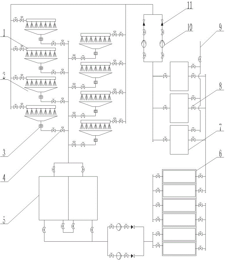
[0031] Such as figure 1 As shown, it includes an aerosol or water spray device 1, a crushing device 3, a sedimentation tank 5, a coarse filter 6, and a fine filter 7; the aerosol or water spray device 1 sprays and cools a steel plate or a steel strip, A large number of iron oxides of different sizes are produced during the process, and the cooling water containing iron sheets enters the sump 2; the crushing device 3 is installed at the lower part of the sump 2, and is connected with a sedimentation tank, a coarse filter, and a fine filter in sequence.

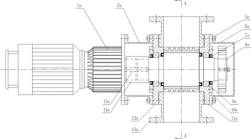
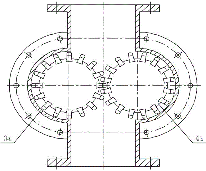
[0032] Such as figure 2 , image 3 , Figure 4 As shown, the crushing device includes a housing 15a, a motor 1a, a pinion shaft 3a, and a large gear shaft 4a. There is a sewage inlet at the top of the housing, and a sewage outlet at the bottom of the housing; the motor 1a is connected with the speed reducer 2a, The outp...


PUM

PropertyMeasurementUnit
pore sizeaaaaaaaaaa

Abstract

The invention relates to a cooling water circulating and recycling system for a normalizing furnace. The cooling water circulating and recycling system comprises crushing devices, settling ponds and filters, wherein the crushing devices are arranged at the lower parts of water collecting sumps; the output ends of the crushing devices are connected with the input ends of the settling ponds; the output ends of the settling ponds are connected with the filters; the filters are matched with aerial fog and water spraying devices; and the filters comprise coarse filters and fine filters. The cooling water circulating and recycling system disclosed by the invention has the beneficial effects that impurities in cooling water are crushed by the crushing devices; the particle size of the impurities in the cooling water can meet the requirement of the aerial fog and water spraying devices by filtering of the coarse filters and the fine filters layer by layer; normal work of spray ports of spray nozzles of aerial fog and water spraying pipes is ensured; and the service life of equipment is prolonged. The cooling water circulating and recycling system is simple in operation; and the cooling water is recycled, so that the operation cost is reduced.

Description

technical field [0001] The invention relates to the technical field of industrial water purification treatment and recycling, in particular to a cooling water recycling system for a normalizing furnace. Background technique [0002] The normalizing furnace is an equipment used for continuous heat treatment of steel plates and strips. Normalizing is normalizing treatment. In order to meet the process requirements of normalizing annealing of high-grade non-oriented silicon steel and high magnetic induction oriented silicon steel, a cooling section of the normalizing furnace is set up to achieve strip cooling through gas mist, air and water spraying. Require. Among them, the nozzle nozzle of the air mist cooling and water spraying device (namely, the air mist and water spraying device) must be very small, about 1mm, in order to achieve better spraying and cooling effects and meet the process requirements. [0003] The existing cooling water systems for industrial furnaces are...

Claims


Application Information

Patent Timeline
Patent Type & Authority Patents(China)
IPC IPC(8): C21D9/573C21D1/28
Inventor 李飞许文峰徐少春高阳
Owner WISDRI WUHAN WIS IND FURNACE
Why Eureka
Try Eureka