Equipment and method for constructing high-pressure rotary jet stiffening pile by using ribbed drilling method

A technology of high-pressure rotary spraying and construction equipment, which is applied to sheet pile walls, foundation structure engineering, construction, etc., can solve the problems of fast mechanical wear, increased steel ball rotation resistance, and labor-intensive, etc., and achieves reduced pile-forming time, shearing The effect of improving shear strength and reducing cement waste

Active Publication Date: 2012-09-12
王忠友
View PDF5 Cites 1 Cited by
  • Summary
  • Abstract
  • Description
  • Claims
  • Application Information

AI Technical Summary

Problems solved by technology

[0017] Manpower-consuming; construction speed is very slow; mechanical wear is very fast; waste of time; drill bits and drill pipes are difficult to replace; the operation process is complicated and there are many procedures; it is not easy to clean; it requires a high professional level
[0018] During the construction process of rotary jet stiffened pile construction equipment in sand layers and other difficult-to-construction grounds, the bearings are not well protected, causing sand to often enter the interior of the bearings, causing them to wear rapidly, increasing the rotational resistance of the steel balls, and even bearing failures. Stalling or derailment of internal rotors
As a result, the steel strand is wound on the transmission drill pipe due to the friction and rotation of the end bearing plate; in addition, in the case of hard ground, the drill tip of the rotary grouting stiffened pile construction equipment has no hard materials and propulsion equipment, so the propulsion during the construction process Difficult; making the construction of jet grouted stiffened piles impossible in harder ground

Method used


Image

  • Equipment and method for constructing high-pressure rotary jet stiffening pile by using ribbed drilling method
  • Equipment and method for constructing high-pressure rotary jet stiffening pile by using ribbed drilling method
  • Equipment and method for constructing high-pressure rotary jet stiffening pile by using ribbed drilling method

Examples


Embodiment Construction

[0048] Embodiment of the present invention is described below in conjunction with accompanying drawing, embodiment does not constitute limitation of the present invention:

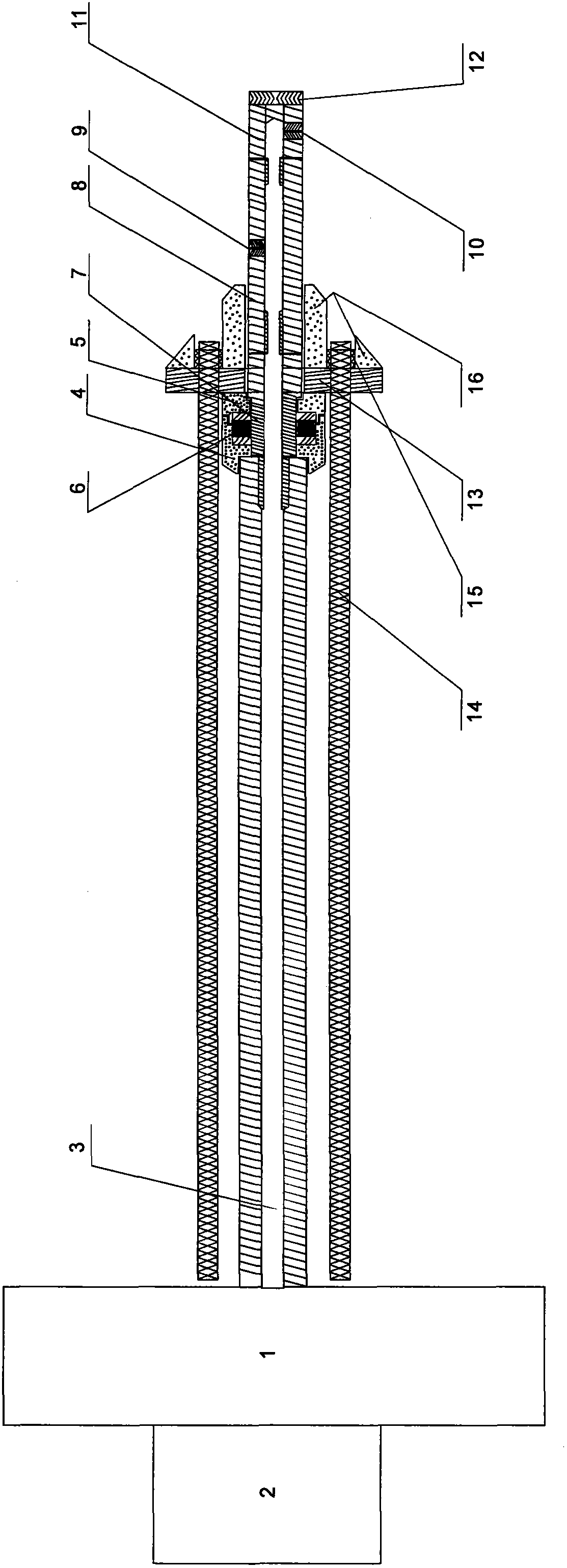
[0049] An end bearing disc 13 is included which adjoins the bearing 6 which has a protective cover. Described bearing 6 has protective cover. The protective cover can effectively protect the bearing.

[0050] The further technical solution of the present invention is: the protective cover is divided into two parts that can be spliced, that is, the rear shell 4 of the bearing protective cover and the front shell 5 of the bearing protective cover. Dividing into two parts allows the inner bearing 6 to be replaced.

[0051] The further technical solution of the present invention is that: the splicing surface between the rear shell 4 of the bearing protection cover and the front shell 5 of the bearing protection cover is a folded surface. The folded surface can effectively prevent sand from entering the bear...


PUM


Abstract

The invention relates to equipment and a method for constructing a high-pressure rotary jet stiffening pile by using a ribbed drilling method. The technical scheme is that: the equipment comprises an end bearing plate which is adjacent to a bearing; the bearing is provided with a protective cover; and a tapered propelling body is arranged on the non-bearing side of the end bearing plate. The equipment also comprises a vibroflot on one side, which is not provided with a drive drill pipe, of a power head. Due to the adoption of the technical scheme, the equipment and the method have the beneficial effects that the bearing is effectively protected; the protective cover is arranged outside the bearing, so that sand cannot enter the bearing; the sectional protective cover has a splicing surface which is a folding surface, and can be split through the splicing surface; the bearing can be replaced, and the sand and the like can be effectively prevented from entering the bearing through the folding surface; the tapered propelling body is arranged on the non-bearing side of the end bearing plate, so that obstacles on a propelling path can be effectively eliminated, and the end bearing plate can be smoothly propelled to finish construction; in addition, the vibroflot is arranged, so that the stratum on the propelling path can be effectively loosened, and the construction can be smoothly finished; and manpower and material resources are saved, work hours are reduced, complex procedures are eliminated, and pore-forming, rib insertion and grouting can be finished at one time.

Description

Technical field: [0001] The invention relates to the field of civil engineering, in particular to construction equipment and a method for high-pressure rotary grouting stiffened piles by drilling with reinforcement. Background technique: [0002] Anchorage technology first appeared in the development and construction of mines, and then matured in the construction of railways, highways and water conservancy. With the continuous development of underground space, anchoring technology has been widely used in the field of construction. At present, the anchoring technology is divided into weathered and broken rock anchoring and weak soil anchoring. Rock pore-forming equipment includes gas-lift rock drills, gas-lift down-the-hole drilling rigs, and geological drilling rigs. Hole-forming equipment for soft soils includes helical bolt rigs, self-tapping screw bolt rigs (directly screwed without grouting) and Luoyang shovels. Anchor reinforcements include ordinary steel bars, prest...

Claims


Application Information

Patent Timeline
Patent Type & Authority Applications(China)
IPC IPC(8): E02D5/46E02D15/04
Inventor 王忠友
Owner 王忠友
Why Eureka
Try Eureka