Super-resolution thermal infrared imager and method for acquiring high-resolution infrared image

An infrared thermal imager, super-resolution technology, applied in the field of infrared thermal imaging

Active Publication Date: 2012-09-12
HUAZHONG UNIV OF SCI & TECH +1
View PDF6 Cites 7 Cited by
  • Summary
  • Abstract
  • Description
  • Claims
  • Application Information

AI Technical Summary

Problems solved by technology

[0005] An object of the present invention is to provide a super-resolution thermal imaging camera without optical scanning components, improve the resolution of infrared images, provide richer image details and better image quality, and enhance the performance of infrared thermal imaging cameras. performance and address the detrimental effects of optical scanning components in existing super-resolution thermal imaging cameras

Method used


Image

  • Super-resolution thermal infrared imager and method for acquiring high-resolution infrared image
  • Super-resolution thermal infrared imager and method for acquiring high-resolution infrared image
  • Super-resolution thermal infrared imager and method for acquiring high-resolution infrared image

Examples


Embodiment 1

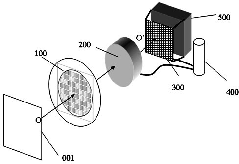
[0062] Such as figure 1 Shown is a basic embodiment of the composition of a super-resolution infrared thermal imaging camera of the present invention.

[0063] A super-resolution thermal imaging camera, comprising an encoding component 100 located at the forefront of the super-resolution thermal imaging camera and centered on the optical axis O-O', for receiving infrared radiation signals emitted by scene 001, and Encode the infrared radiation signal; in the rear of the encoding assembly 100 along the optical axis OO' direction, an infrared optical system 200 and an area array infrared detector focal plane 300 are sequentially installed; the infrared optical system 200 is used to pass through the encoding assembly The infrared radiation of 100 is converged on the target surface of the focal plane 300 of the area array infrared detector to enhance the signal-to-noise ratio of the infrared image, and is used for the protection window of the focal plane 300 of the area array inf...

Embodiment 2

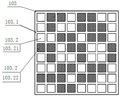
[0066] Example 2 : The difference with embodiment 1 is: this embodiment is such as image 3 As shown, it is a better technical solution. Among the N×N square diaphragms 103.2, N is equal to 8, that is, there are 8×8 equal to 64 square diaphragms 103.2. Among them, the high light transmittance film 103.21 and the low light transmittance The light transmittance ratio of the high-efficiency diaphragm 103.22 is 10: 1; the number of low light transmittance diaphragms 103.22 is 31, which is 1.92 / 4 of the total number of 64 square diaphragms 103.2, which is nearly half, and the remaining 33 square The diaphragm 103.2 is a high light transmittance diaphragm 103.21; the substrate 103.1 of this embodiment is a silicon substrate.

Embodiment 3

[0067] Example 3 : Different from Embodiment 1: among the N×N square diaphragms 103.2 of the present embodiment, N is 24, that is, there are 24×24 equal to 576 square diaphragms 103.2, wherein, the high light transmittance diaphragm 103.21 and the low The light transmittance ratio of the light transmittance diaphragm 103.22 is 10:0.8; the number of low light transmittance diaphragms 103.22 is equal to 1 / 4 of the total number of square diaphragms 103.2, and the remaining square diaphragms 103.2 are high light transmittance diaphragms 103.21; the substrate 103.1 in this embodiment is a silicon substrate.


PUM


Abstract

The invention relates to a super-resolution thermal infrared imager and a method for acquiring a high-resolution infrared image. The thermal infrared imager comprises an encoding assembly arranged at the most front end, an infrared optical system and a surface array infrared detector focal plane are sequentially arranged at the back of the encoding assembly along the direction of an optical shaft, and a refrigerator is used for refrigerating the surface array infrared detector focal plane and the infrared optical system to enable the both to keep a low-temperature working state. The method for acquiring the high-resolution infrared image comprises the following steps of: converging encoded infrared radiation, transmitting an analog electric signal converted by an infrared radiation signal, converting the analog electric signal, saving an infrared image signal and the like, finally fusing multiple groups of infrared image signals to form the high-resolution infrared image. The super-resolution thermal infrared imager and the method have the advantages of no optical scanning component, improved a resolution performance of the thermal infrared imager, the reliability and the stability of the thermal imager and the image quality of a whole imaging device, light weight, low realization difficulty and low manufacturing and using costs.

Description

Technical field [0001] The invention involves a super -resolution infrared thermal imageor in an optical scanning component and the method of obtaining high -resolution infrared images with it, which is the field of infrared thermal imaging technology. Background technique [0002] In the photoelectric imaging system, image resolution is an important indicator.Higher resolution means more image details, which is of great significance for the application of target detection, recognition, aerospace remote sensing.Especially for infrared thermal portraits, the performance of improvement resolution is more significant.This is because the resolution of infrared detectors is relatively low, resulting in the lack of resolution and details of infrared images, which limits the performance improvement of infrared thermal imageriors. [0003] There are two basic factors of restricting image resolution: one is optical diffraction limit resolution, and the other is the detector sampling frequ...

Claims


Application Information

Patent Timeline
Patent Type & Authority Applications(China)
IPC IPC(8): G01J5/10H04N5/33
Inventor 余徽陈福胜张智杰王晨晟
Owner HUAZHONG UNIV OF SCI & TECH
Why Eureka
Try Eureka